40/60
♦ Avoid coiling the connection to minimise inductive effects that could affect welding. Connect the other end of
connection BA to the wire feeder (see g. 5).
11
20
19
Fig. 5
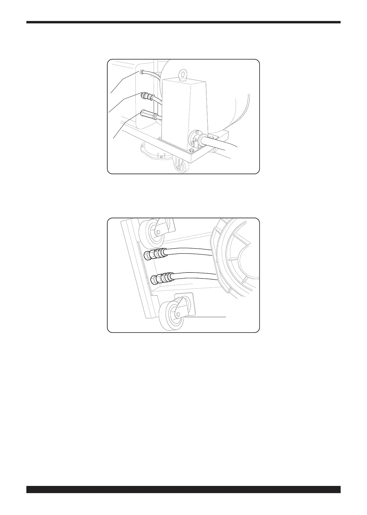
♦ The coolant uid hoses must be connected to the quick-tting valves located below the base of the wire feeder
(see g. 6), by observing the colour coding on the trolley front side.
Fig. 6
Note on gas connection
Carefully read the sections “Explosions”, “Hazardous gases and vapours” and “Gas cylinders” in General Warnings
code 3301151.