57/60
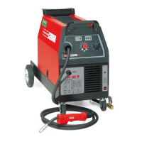
In order to weld in MIG Manual mode always choose the curve for the wire/diameter/gas to be used beforehand.
Set the motor m/min (metres per minute). Select the welding voltage shown on the display, press the knob for longer
than 1 second. This will display the set voltage in relation to the curve m/min. The machine adjusts to the V (voltage)
and m/min (metres per minute) settings.
Now the wire speed can be increased without changing the arc voltage. This process is active only for welding in
Short mode�
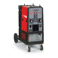
8 MMA WELDING
Connect the electrode holder cable connector to socket 16 and the earth cable connector to connector 4 (observing
the polarity stated by the electrode manufacturer).
In order to prepare the machine for MMA welding, follow the instructions previously described in the menu.
9 ERROR CODES
Error management is divided into two categories:
1) Hardware errors [E]. These cannot be reset and require the power source to be restarted. These are displayed on
the screen with a red background.
2) Alarms [W] linked to an external condition that can be reset by the user and does not require the generator to be
restarted.
These are displayed on the screen with an amber background.
Code Type Error Description Action
2 [E] EEPROM error detected by the
power source internal board
Switch the power source off and on. If the problem
persists, contact technical assistance.
6 [E] Communication error detected
by master panel board on
CAN-bus
Switch the power source on and off. If the error persists,
contact technical assistance.
9 [E] Communication error detected
by slave board on CAN-bus
Switch the power source on and off. If the error persists,
contact technical assistance.
10 [E] Power output nil (I=0A, V=0V) Hardware error, contact technical assistance. Probable
break in inverter circuit of primary winding or secondary
unit
11 [E] Overload at output Hardware error, contact technical assistance.
14 [E] Undervoltage error detected
on inverter control board.
Check machine supply voltages. If the problem persists,
contact technical assistance.
20 [E] Interlock signal absent Switch the power source off and on. If the problem
persists, contact technical assistance
22 [E] Hardware key not readable Switch the power source on and off. If the error persists,
contact technical assistance.
24 [E] Error during reprogramming of
the EPLD or FPGA
Switch the power source on and off. If the error persists,
contact technical assistance.
24 [E] Error during reprogramming of
the EPLD or FPGA
Switch the power source on and off. If the error persists,
contact technical assistance.
25 [E] Excessive primary winding
current error
Switch the power source on and off. If the error persists,
contact technical assistance. Probable break in output
diodes or primary winding inverter circuit.
26 [E] Time not set or battery at Turn the power source off and on. Replace the battery
on the panel board and contact technical assistance if
the error persists.