42/60
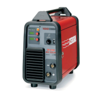
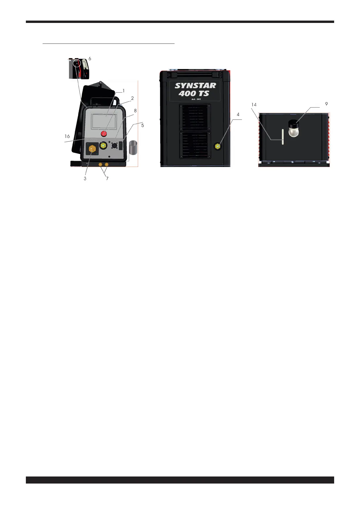
4 CONTROLS LOCATED ON FRONT PANELS
1 DISPLAY�
This displays both the welding parameters and all the welding functions
2 KNOB
Selects and adjusts welding functions and parameters
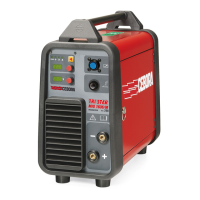
3 CENTRAL ADAPTER
This is where the welding torch is to be connected
4 EARTH CABLE OR SOCKET
Socket (-) for connecting the earth cable connector
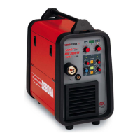
5 CONNECTOR
DB9 type (RS 232) connector to be used for updating the welding programs
6 CONNECTOR
USB-type connector to be used for updating the welding programs
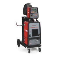
7 QUICK-FITTING VALVES
Connect the red and blue hose of the welding torch (red with red, blue with blue)
8 CONNECTOR
This is where the control cable of the Push Pull welding torch is connected
9 TANK CAP
14 SLOT
Slot to inspect the coolant uid level
16 SOCKET (+)
Socket for connecting the electrode clamp in MMA welding