page 22 www.centsys.com
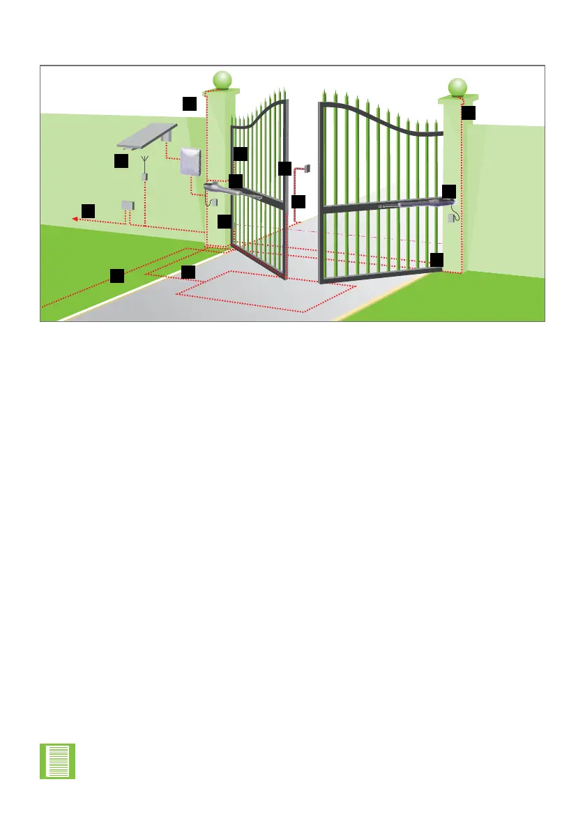
5.8 Cabling Requirements
INSTALLATION PREPARATIONSECTION 5
FIGURE 16. CABLING REQUIREMENTS
Legend
1. 90V - 240V AC Mains cable via Mains isolator
1
switch (3 core LNE 0,5mm
2
)
2
,
or low-voltage 16V AC battery charger supply
3
(2 core 1,5mm²).
2. Intercom cable (n1 + 6 core) to house.
3. Master Motor (MTR M) or Slave Motor (MTR S) cable.
(Minimum, 2 core 1.5mm
2
+ 4 core 0,22mm
2
multi-stranded)
4
.
4. Optional radio receiver cable (3 core 0,5mm
2
multi-stranded, optional)
5
.
5. Optional Pedestrian Keyswitch (2 core 0,5mm
2
multi-stranded) or optional keypad
(3 core 0,5mm
2
multi-stranded).
6. Optional, but recommended infrared Safety Beams (3 core 0,5mm
2
multi-stranded
or 4 core 0.5mm
2
for CE compliance).
7. Optional intercom cable (n2+2 core 0,5mm
2
multi-stranded) to gate station.
8. Optional electric lock (2 core 0.5mm
2
).
9. Optional Pillar Light cable (3 core, size according to power regulations).
10. Optional ground loop for free-exit
(1 core 0.5mm
2
multi-stranded - silicone-coated)
6
.
11. Optional solar panel
(2 core 1.5mm
2
Cabtyre or G.P. in Conduit).
1. Mains isolator supplied with Vx SMART Wall Box.
2. Increase cable thickness if Pillar Lights are to be installed.
3. Screened cable is always recommended to provide better protection against lightning - earth one end of screening.
4. Please use V-Series SMART cabling. Order reference: CABLEVEC68 (10M maximum from Vx-Series controller to
operator).
5. For optimum range an external receiver can be mounted on the wall.
6. Consult manufacturer of loop detector for specic details.
5
6
4
1
2
3
8
9
9
7
• All cables must be routed in conduit unless underground cable is being used
• Mains isolator must be less than one metre from the operator
• Safety Beams are always recommended: i5, Photon or Photon SMART
5
6
4
1
3
11
9
9
8
10
7
2
3