Do you have a question about the CENTURION SYSTEMS VANTAGE 400 SMART and is the answer not in the manual?
Lists advanced features of the Vx SMART logic controller, including UI, setup, speed adjustment, and safety.
Detailed safety warnings and instructions for installers, covering qualifications, operation, modifications, and power handling.
Critical warnings, including not running the operator directly from the battery, to prevent damage.
Emphasizes the necessity of proper earthing for effective surge protection of the unit.
Provides physical dimensions for the VANTAGE 400 SMART and VANTAGE 500 SMART operators.
Details technical specifications for the main operator, including voltage, motor, and battery charger.
Continues operator specs and details SMART Controller and Power Supply specifications.
Tables showing maximum allowable gate mass for VANTAGE 400/500 SMART based on swing angle and length.
Details operational wind speeds for gate operation based on leaf dimensions and coverage.
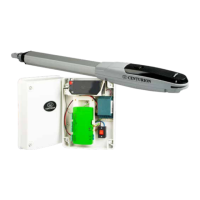
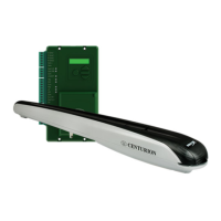
Identifies main kit components and Vx SMART Wall Box parts, including controller and battery.
Displays a comprehensive list of tools and equipment required for installation.
Covers general installation considerations, safety equipment, gate conditions, and critical battery warning.
Explains the procedure for measuring gate opening angle using Z-Value and relevant tables.
Illustrates side wall limitations for inward-opening gates, specifying minimum wall clearance.
Depicts pillar hinge depth limitations and provides specifications for 90° inward-opening gates.
Describes through-wall, chemical anchor, and welding methods for mounting the wall bracket.
Details sleeve anchor and rawl bolt methods for mounting the wall bracket.
Explains welding and through-bolt methods for mounting the gate bracket.
Provides a legend for understanding cabling components and illustrates the overall cabling layout.
Lists critical requirements for ensuring reliable operation of the VANTAGE SMART operator.
Guides on new site installations, gate mass checks, and defines key terms like E-Value.
Presents gate geometry tables for VANTAGE 400 SMART based on opening angles.
Presents gate geometry tables for VANTAGE 500 SMART based on opening angles.
Guides on determining wall bracket height and modifying the bracket via cutting and welding.
Details fitting the gate bracket, supporting the operator, and temporarily holding the bracket.
Explains operator positioning, securing the origin clamp, and methods for securing the gate bracket.
Guides on outward-opening installations, gate mass checks, and references geometry tables.
Presents gate geometry tables for VANTAGE 500 SMART based on outward opening angles.
Guides on determining wall bracket height and modifying the bracket via cutting and welding for outward opening.
Details fitting the gate bracket, supporting the operator, and temporarily holding the bracket for outward opening.
Explains operator positioning, securing the origin clamp, and methods for securing the gate bracket for outward opening.
Covers secure wall box mounting and essential safety precautions before electrical work.
Recommends using junction boxes and forming a 350mm cable loop for operator wiring.
Explains wiring diagrams for motors and ancillary devices, and the meaning of symbols used.
Provides a wiring diagram for connecting the Master Operator to the Vx SMART Controller.
Provides a wiring diagram for connecting the Slave Operator to the Vx SMART Controller.
Illustrates wiring for i5 closing safety beams to the Vx SMART Controller.
Illustrates wiring for double i5 closing safety beams to the Vx SMART Controller.
Illustrates wiring for i5 opening safety beams to the Vx SMART Controller.
Illustrates wiring for PHOTON closing safety beams to the Vx SMART Controller.
Illustrates wiring for double PHOTON closing safety beams to the Vx SMART Controller.
Illustrates wiring for PHOTON opening safety beams to the Vx SMART Controller.
Instructions on configuring up to three sets of Photon SMART Wireless Safety Beams.
Shows the wiring connection for the GLX900 Electronic Lock to the Vx SMART Controller.
Highlights the need for an interposing relay when wiring Maglocks to the controller to prevent demagnetization.
Illustrates wiring for the status LED on the POLOphone Intercom to the Vx SMART Controller.
Lists app configurations for the external radio receiver (TRG) and loop detector (FRX).
Lists app configurations for the Holiday Lockout Keyswitch/Keypad.
Lists app configurations for the Pedestrian Keyswitch.
Lists app configurations for the G-ULTRA device.
Provides wattage specifications for solar panels (20W-150W) and brackets.
Lists app configurations for the Pillar Light Pushbutton.
Shows the wiring diagram for the pillar light, including relay coil and 240V contact.
Table detailing fuse types and ratings for the main control card, auxiliary supply, and charger.
Shows QR code and minimum requirements for commissioning the system via the mobile app.
Stresses user training on safe operation, understanding features, and awareness of hazards.
Disclaimer regarding product design, intended use, and potential dangers from misuse.
Information on online product registration and conditions that may void the warranty.
| Maximum Gate Mass | 400kg |
|---|---|
| Maximum Gate Length | 4m |
| Duty Cycle | 50% |
| Ingress Protection | IP54 |
| Battery Backup | Yes |
| Motor Type | DC |
| Control Options | Remote Control, Keypad |