EasyManuals Logo

Cervis TM70 User Manual

Default Icon
37 pages
To Next Page IconTo Next Page
To Previous Page IconTo Previous Page
Page #15 background imageLoading...
Page #15 background image
System User Manual
2007-2016 Cervis, Inc.
11
Note: If necessary, it is possible to improve signal reception by using the extension
cables and external antenna kit. See Figure 6 below.
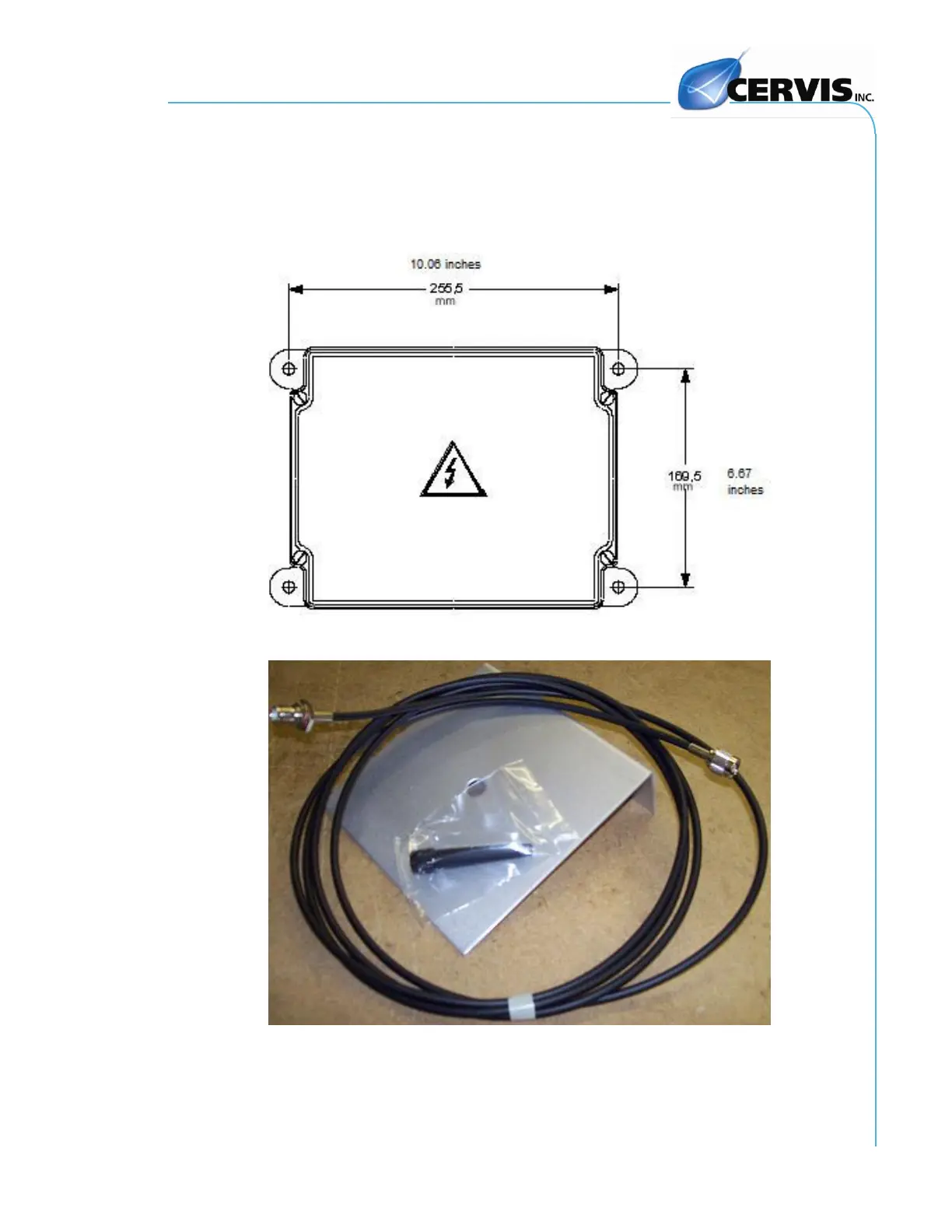
1. Find a suitable location for the receiver with clear access to the
transmitter radio signal. Figure 5 below shows the footprint of the receiver
and illustrates the distance between the mounting holes.
Figure 5. Receiver Footprint
J501 (Antenna) J502 (Cable) J503 (Bracket)
Figure 6. Receiver Antenna with Extension Kit

Table of Contents

Other manuals for Cervis TM70

Questions and Answers:

Question and Answer IconNeed help?

Do you have a question about the Cervis TM70 and is the answer not in the manual?

Cervis TM70 Specifications

General IconGeneral
BrandCervis
ModelTM70
CategoryRemote Control
LanguageEnglish