TM70 Handheld Wireless Remote Control
U003.6.0-TM70_HH_SYS-R
4.2.1 LCD Option Power Level Display
Transmitters with the LCD option indicate the battery power level by showing
segments—black dashes—in the display. The more dashes shown, the more charged
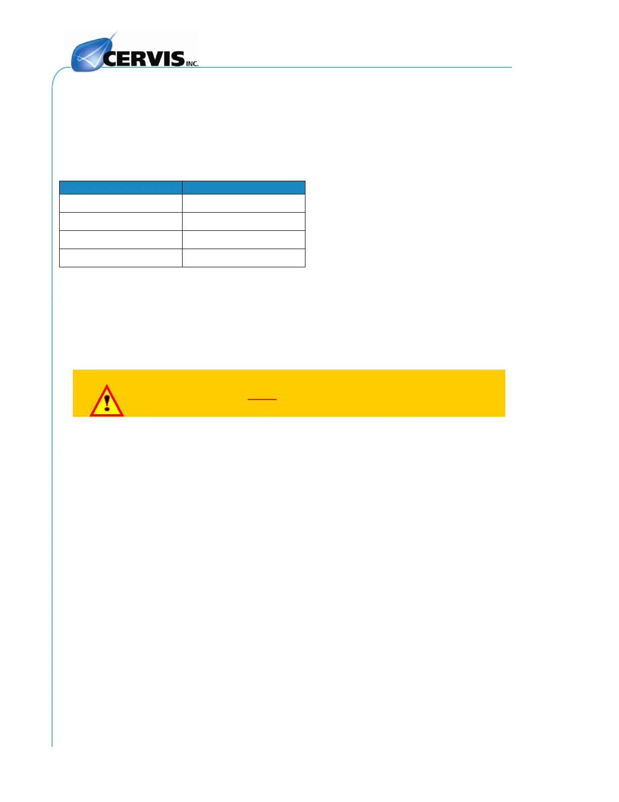
the battery. Power levels are interpreted in Table 5.
Table 5. LCD Power Level Interpretation
Note: The transmitter will automatically go to STAND BY mode after four (4)
minutes of inactivity. Standby mode is indicated by 3-second green LED
pulses. Press the START Button to restart the transmitter. The 4-minute
default can be changed or eliminated through a software modification. If a
change is desired, please contact Customer Service.
Keep in mind at all times that you are controlling a moving piece
of machinery. You must strictly adhere to the safety instructions
described in Section 2.0 of this manual.
4.3 Programming a Spare Transmitter
If a transmitter is damaged, it is possible to quickly restore service by transferring the
EP70 Memory Module EEPROM from the original damaged transmitter to a similar
spare transmitter. This ensures that you use the exact parameters of the original in the
spare. The EP70 Memory Module EEPROM is easily accessible from the exterior of the
transmitter. To transfer the EP70 Memory Module:
4.3.1 Transfer EP70 From Transmitter to Spare Transmitter
1. The EP70 module is a part of the cover located on the back of the
transmitter. Turn the damaged unit over and remove the two screws as
shown in Figure 9A. If there is an EEPROM in the spare transmitter,
remove the cover screws on it, too.
2. Extract the EP70 module from the damaged transmitter as shown in
Figure 9B. Handle module during the transfer by touching only the cover;
avoid touching the actual EEPROM located beneath the cover.
3. Install the original transmitter EP70 module into the spare transmitter. The
module is keyed so that it will only fit in one way.
4. Install the cover screws on the spare transmitter.