TM70 Handheld Wireless Remote Control
U003.6.0-TM70_HH_SYS-R
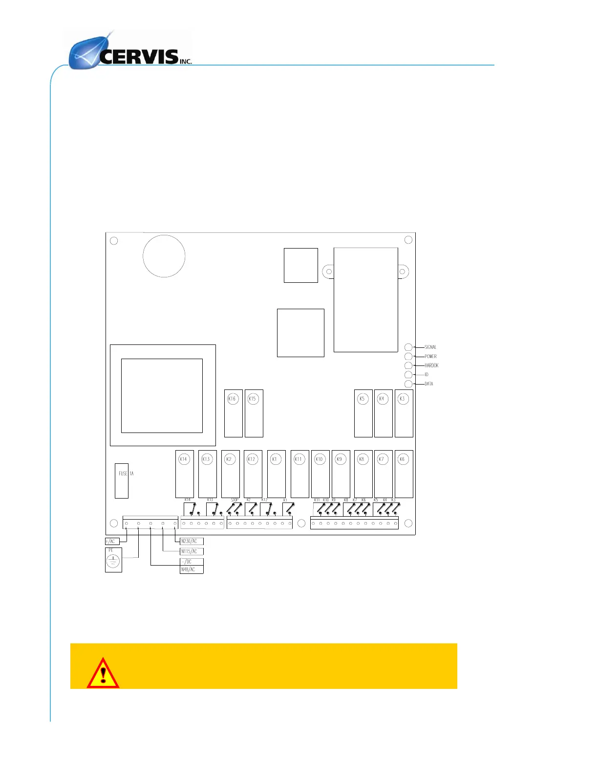
2. Follow the Outputs Diagram supplied with the system to connect the
power supply and the receiver outputs on the relay board plug-in
terminals. The Output Diagram indicates the relationship between the
transmitter commands and the receiver outputs.
The STOP relays K15 and K16 are in series and must be connected to the
main contactor coil circuit.
The K2/START is activated once the Warning/START command is held
down.
The K1/SEC relay is a security relay. It is activated when certain commands
predefined as Active—commands that give rise to movements—are
activated.
Figure 7. Main Board Connections, Relays, and LEDs
3. Select the appropriate voltage on the receiver.
4. Be certain to connect the ground cable.
Use only fireproof cables for connections.