EasyManuals Logo

Cervis TM70 User Manual

Default Icon
37 pages
To Next Page IconTo Next Page
To Previous Page IconTo Previous Page
Page #31 background imageLoading...
Page #31 background image
System User Manual
ļƒ“2007-2016 Cervis, Inc.
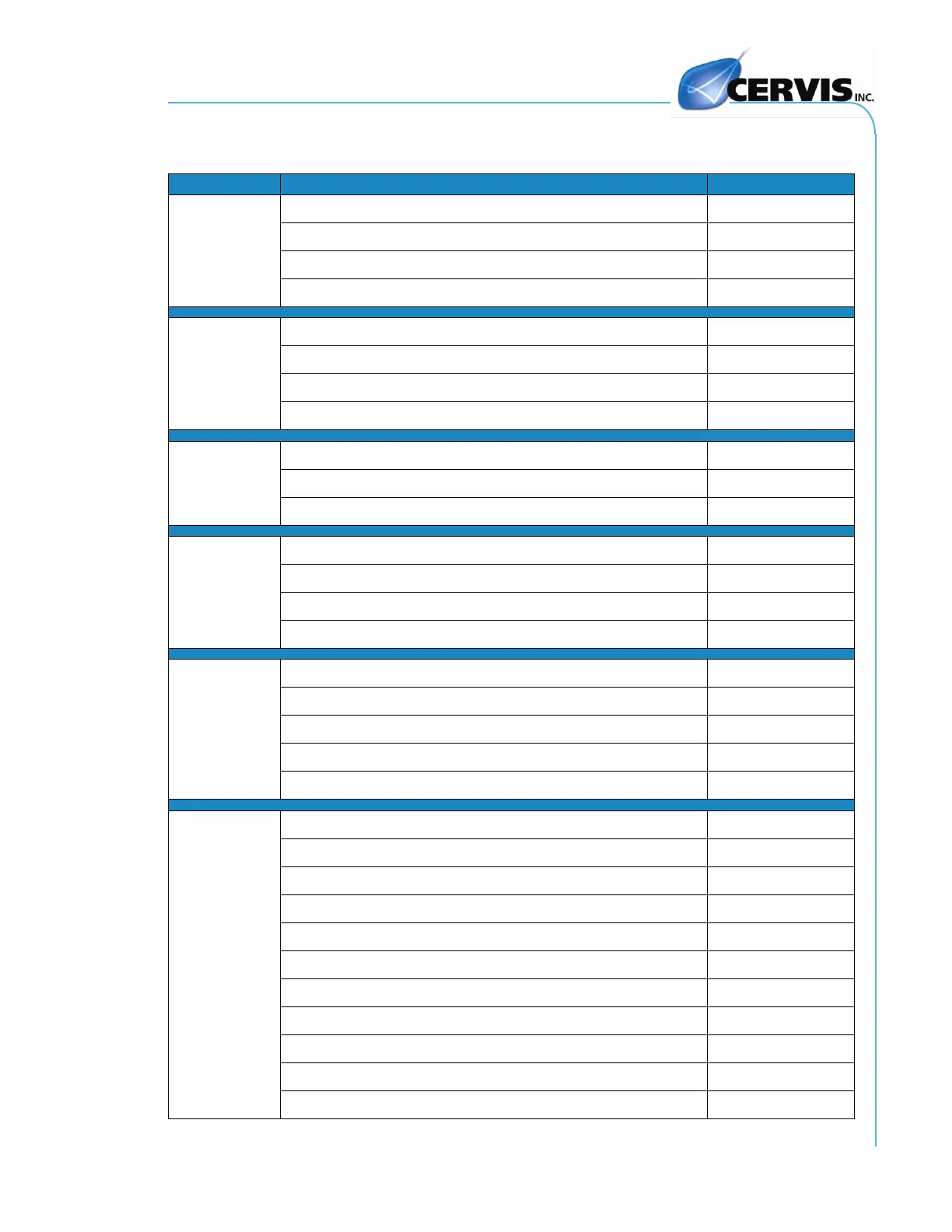
27
5.4 Spare Parts
Table 9.Available Spare Parts
Item
Part
Code
Transmitter
TM70/1
2301090
TM70/2
2301091
TM70/1 with Display & IR Sensor
2301090-B4-DLA
TM70/2 with Display & IR Sensor
2301091-B4 DLA
Transmitter
Boards
LE71/915
2303881
LE71/915/DLA (units with display or IR)
2303901
LE72/915
2303884
LE72/915/DLA (units with display or IR)
2303904
Receivers
R70/13
2301092
R70/21
2301093
R70/29
2305087
Receiver
Boards
LR71/915 (120VAC)
2303887
LR71DC/915 (24VDC)
2303893
LR72/915 (120VAC)
2303890
LR72DC/915 (12VDC)
2303896
Electronic
Circuits
R8 CAN (8 relay)
2303739
IN 0-10V
2303755
IN 0-450P (expansion)
2303758
EP70 EE-Prom
2303743
EE-prom modification
2300300
Misc. Parts
Pushbutton P70
2303670
Pushbutton cover CP70
1152023
Spring return switch 1-0-1 M70
2303770
Maintained switch 1-0-1 S70
2303760
Key lock K60
2300170
Emergency STOP pushbutton EMS60
2305127
Upper part PS70/1 SM
2303780
Upper part PS70/2 SM
2303790
Upper part PS70/1 DLA (display/IR, Stop, and buttons)
2303801
Upper part PS70/2 DLA (display/IR, Stop, and buttons)
2303811
Lower part PI70/1
2303677

Table of Contents

Other manuals for Cervis TM70

Questions and Answers:

Question and Answer IconNeed help?

Do you have a question about the Cervis TM70 and is the answer not in the manual?

Cervis TM70 Specifications

General IconGeneral
BrandCervis
ModelTM70
CategoryRemote Control
LanguageEnglish