TM70 Handheld Wireless Remote Control
U003.6.0-TM70_HH_SYS-R
If any of the relays are not activated, the problem is associated with the
remote control equipment. Observe the status of the LED’s and reference
Table 8 to determine the problem source.
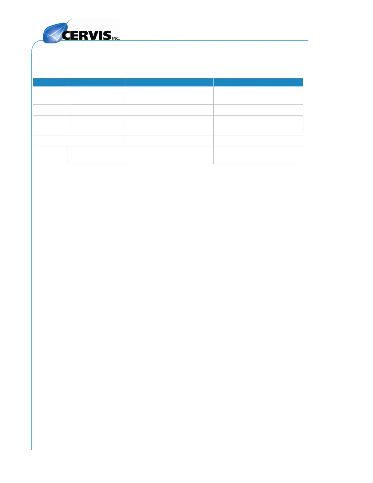
Table 8. Receiver Status LED Fault Identification
RF signal detection in
SCANNING Mode
The receiver is not receiving
RF signals
Is receiving the correct data
from a TM701
1
DATA and ID LED’s show a weak flashing when data and the ID code are received correctly but the Start
command has not yet been received. Once START Button is pushed ON the DATA and ID LED’s will show the
standard strong flashing.
5.3 Returning Equipment for Repair
If you find a problem with the equipment:
1. Contact our Customer Service.
2. Discuss your problem with the Cervis technician. In many cases the
problem can be resolved over the telephone and thus not require you to
return any equipment.
3. When equipment is determined to need service, the technician will issue
an Return Material Authorization (RMA) number to you.
4. Return the defective device to our Customer Service Department. Please:
Include a description of the problem and the status of the LEDs.
Clearly mark your issued RMA number on the outside of the package.
Note: Please address all equipment returned to Cervis, Inc. to the attention of our
Technical Service Department, together with a description of the problem and
the status of all LED’s. It is our intention to make the necessary repairs quickly
and return the system to you as soon as possible.
Note: If the transmitter becomes inoperable, a spare can be quickly substituted by
following the instructions in APPENDIX A.