CESSNA
MODEL
172S NAV
III
SECTION 7
AIRPLANE AND SYSTEMS DESCRIPTION
WING FLAP SYSTEM
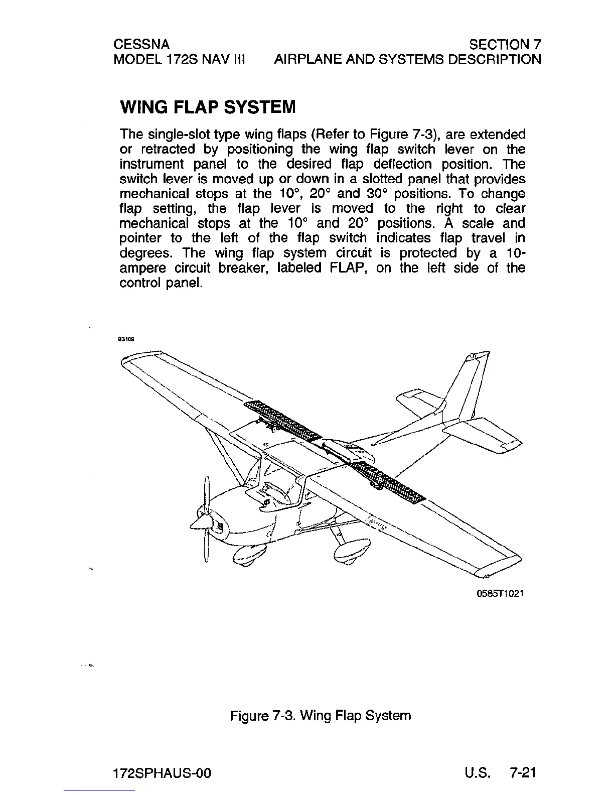
The single-slot type wing flaps (Refer to Figure 7-3), are extended
or retracted by positioning the wing flap switch lever
on
the
instrument panel to the desired flap deflection position. The
switch lever is moved
up
or down
in
a slotted panel that provides
mechanical stops at the
10°, 20° and 30°
pOSitions.
To change
flap setting, the flap lever
is
moved to the right to clear
mechanical stops at the
10° and 20° positions. A scale and
pointer to the left of the flap switch indicates flap travel
in
degrees. The wing flap system circuit is protected
by
a 10-
ampere circuit breaker, labeled FLAP,
on
the left side of the
control panel.
B31~
0585T1
021
Figure 7-3. Wing Flap System
172SPHAUS-00
U.S.
7-21
 Loading...