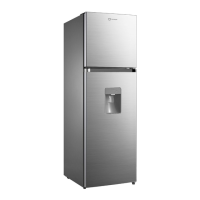
The AC input power is reduced in voltage by SMPS control chip and filtered off wave by the inductance-
capacitance filter, then output the DC 12V power which will mainly power the relay that controls strong
current. Relay is used to control the strong current loaded switches of compressor, ice maker and defrost
heater. The DC 12V power will output stable 5V electricity after passing through the adjustor 7805, to
power for the main control chip and thus monitor the temperature changes in refrigerator.
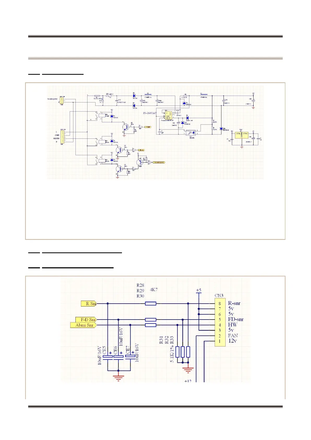
It’s conducted by the sensor, making use of the characteristics that resistance value reduces as the
temperature increases, and the thermistor that has temperature coefficient of resistance in medium