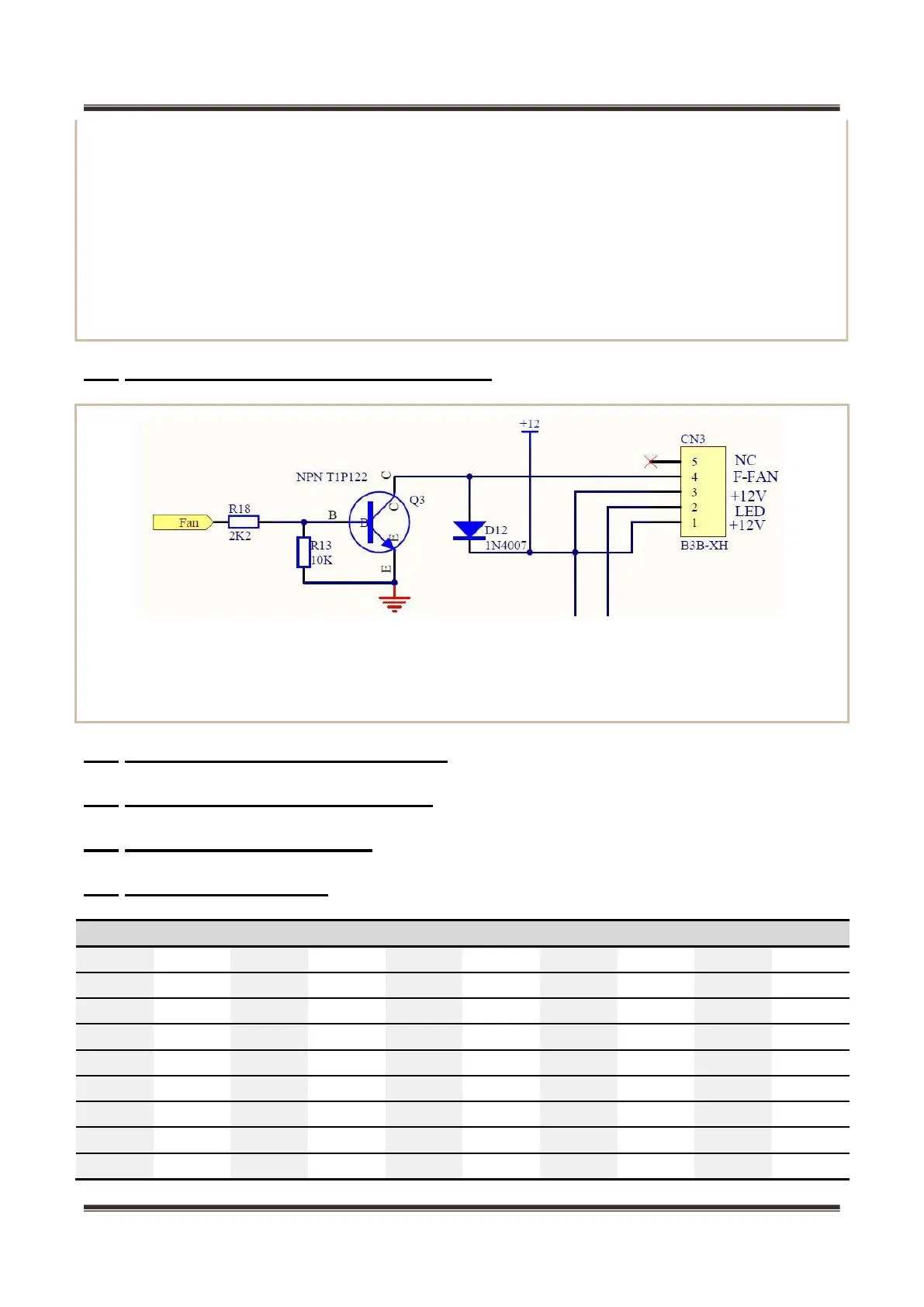
The fan in the freezing chamber is running when the compressor is operating. Check 12V and FAN to see
if there is a voltage of 12V. When in normal operation, the fan is in low level and the voltage between 12V
and FAN is more than 11V. If there’s no voltage when the compressor is in operation, fan motor or electric
control panel can be replaced.
10.4
Fan motor circuit of the freezing chamber
10.5
Refrigerator fan motor circuit (None)
10.6
Condenser fan motor circuit(None)
10.7
Damper motor circuit(None)
10.8
Sensor resistance(R/T)
Tx(℃) R(KΩ) Tx(℃) R(KΩ) Tx(℃) R(KΩ) Tx(℃) R(KΩ) Tx(℃) R(KΩ)
temperature.
The characteristic that resistance value reduces as the temperature increases is deemed to have
negative slope or negative temperature coefficient (NTC), and such thermistor is called as NTC thermistor.
The resistance value changes sensitively with temperature and typically changes 7% ~ 3% per degree
centigrade. Sensor used in the refrigerator is NTC thermistor.
There is following computing formula for the sensor:Sampling voltage / reference voltage =
R1 / (RNTC + R1)
AD value / reference AD value = R1 / (RNTC + R1)