70
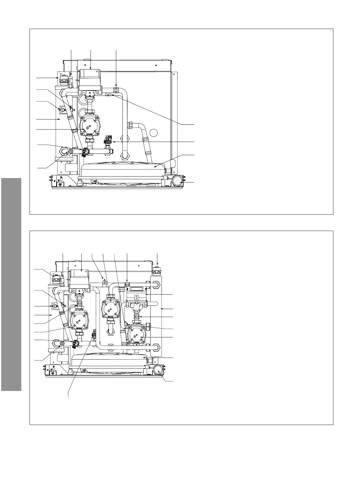
Installation of the internal unit
ARIANEXT COMPACT
Overall view FSP 1 ZONE
Overall view FSP 2 ZONES
1
13
14
2
3
11
10
12
4
5
7
6
9 8
1
23
21
22
2
3
16
1718 13 121415
4
9
10
7
6
11
5
8
19
20
1. Circulator
2. Safety valve 3 bar
3. Discharge valve
4. Manometer
5. Pressure switch
6. Expansion vessel
7. Modulating pump Zone 2
8. Return temperature sensor zone 2
9. Flow temperature sensor zone 2
10. Hydraulic separator
11. Mixing valve
12. Automatic air purge
13. Flow temperature sensor zone 1
14. Return temperature sensor zone 1
15. Modulating pump Zone 1
16. Temperature sensor (fl ow to the installation)
17. Diverter valve
18. Discharge valve
19. Automatic air purge
20. Safety thermostat (automatic switch)
21. Safety thermostat (manual switch)
22. Heating back-up resistance (2 kW + 2kW)
23. Temperature sensor (return from the installation)
1. Circulator
2. Safety valve 3 bar
3. Discharge valve
4. Manometer
5. Expansion vessel
6. Pressure switch
7. Return temperature sensor zone 1
8. Flow temperature sensor zone 1
9. Diverter valve
10. Discharge valve
11. Automatic air purge
12. Safety thermostat (automatic switch)
13. Safety thermostat (manual switch)
14. Heating back-up resistance (2 kW + 2kW)
 Loading...