22
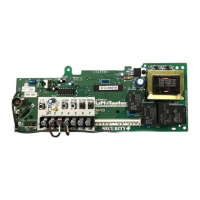
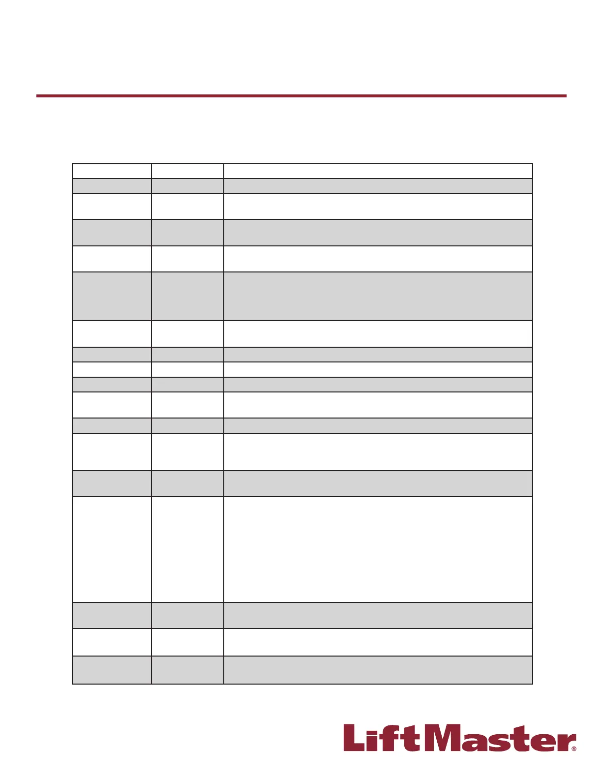
The industrial duty logic boards (5.0, 4.0, 3.0) have several LEDs to assist in the installation and troubleshooting of the
operator. The following chart should assist in verifying the operator is functioning properly. Turn the selector dial to
DIAGNOSTIC to keep the door from moving while troubleshooting.
LED COLOR DEFINITION
Power Green Indicates power is being generated for the logic board.
Stop Green Indicates a closed circuit between Common terminal 4 and Stop terminal 5.
Pressing stop should turn off this LED.
Open Yellow Indicates a closed circuit between Common terminal 4 and Open terminal 7.
Pressing the open button should turn ON this LED.
Close Yellow Indicates a closed circuit between Common terminal 4 and Close terminal 6.
Pressing the close button should turn ON this LED.
LMEP
(Photoelectric
sensors) (CPS-U,
CPS-UN4)
Green Solid on indicates LMEP learned. Flashing indicates sensors need to be
re-connected or activated, or unlearned if removed**. Solid off indicates no
sensors learned.
Timer Defeat Yellow Solid on indicates a closed circuit between common and terminal 12.
Timer-To-Close will not close.
OLS Yellow Pressing the Open Limit Switch should turn ON this LED.
CLS Yellow Pressing the Close Limit Switch should turn ON this LED.
SLS Yellow Pressing the Sensing Limit Switch should turn ON this LED.
Edge Yellow Indicates a closed circuit between common and terminal 8. Pressing the edge
should turn ON this LED.
Mid-Stop Yellow Solid on indicates door is stopped on mid-stop.
Timer Enabled Green Solid on indicates TIMER is programmed and will activate from open or mid
stop position. Flashing indicates TIMER is counting down and door will close
after preset time. Each fl ash represents 1 second of programmed time.
SBC Yellow Indicates a closed circuit between common and terminal 1. Pressing the
single button control station should turn ON this LED.
MAS Yellow Indicates the Maintenance Alert System has been activated or an error code
has been triggered. See inside cover of the operator.
NOTE: After a power cycle, the board will fl ash a series of lights, and then
fl ash the fi rmware Rev. on the MAS light. The fi rmware revision will always
be fl ashed as X.Y.; e.g. current version is 8.12 which would fl ash as; 8 blinks,
pause, one blink, pause, 12 blinks. The fi rmware version is printed on the
label of each L5 board. These blinks should not be confused with an error code
which would continue to fl ash repeatedly.
Relay A Yellow Indicates open or close command has been given to the motor. LED turns on
when OPEN/CLOSE button is pressed.
Relay B Yellow Indicates open or close command has been given to the motor. LED turns on
when OPEN/CLOSE button is pressed.
DATA* Green Indicates communication between the Logic 5.0 board and optional
TLS1CARD.
B
Diagnostic Chart
Industrial Duty Logic Operators
* Logic 5.0 ONLY
** To unlearn, turn the selector dial to DIAG. Press and hold the STOP button until the MAS LED fl ashes (5 fl ashes).
Return the selector dial to the desired wiring type.