56
*NOTE: Black and gray positions vary by model.
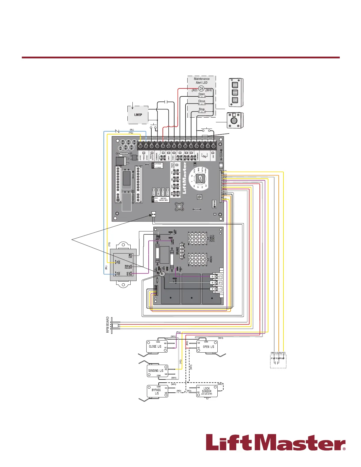
Refer to the installation
manual for LiftMaster
Monitored Entrapment
Protection (LMEP)
device connections
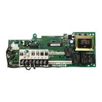
NOTE: Lock Sensor is provided on
Models DJ and DH only, red wire from
main harness connects to NC on Bypass
L/S and to NO on LOCK SENSOR Switch.
White wires connect the COM on BYPASS
L/S and LOCK SENSOR Switch to NC on
Open L/S.
NOTE: The Lock Sensor Switch is
located in the chassis.
NOTE: 32 Vdc power supplied
from White and Yellow wires
located within the electrical box.
External Radio
Receiver
Remove Jumper
To Install External
Door Interlock
3-Button Control Station
Open/Close
Single Button
Ancillary
Sensing
Edge
Hoist Interlock
When Present
TMR DEF
SWITCH
NOTE: Logic 5.0 three-phase
operators built before February
2016 do not have these
connectors
F
Wiring Diagrams
Logic 5.0 - Three Phase