MOUNT POWER SUPPLY (CONTINUED)
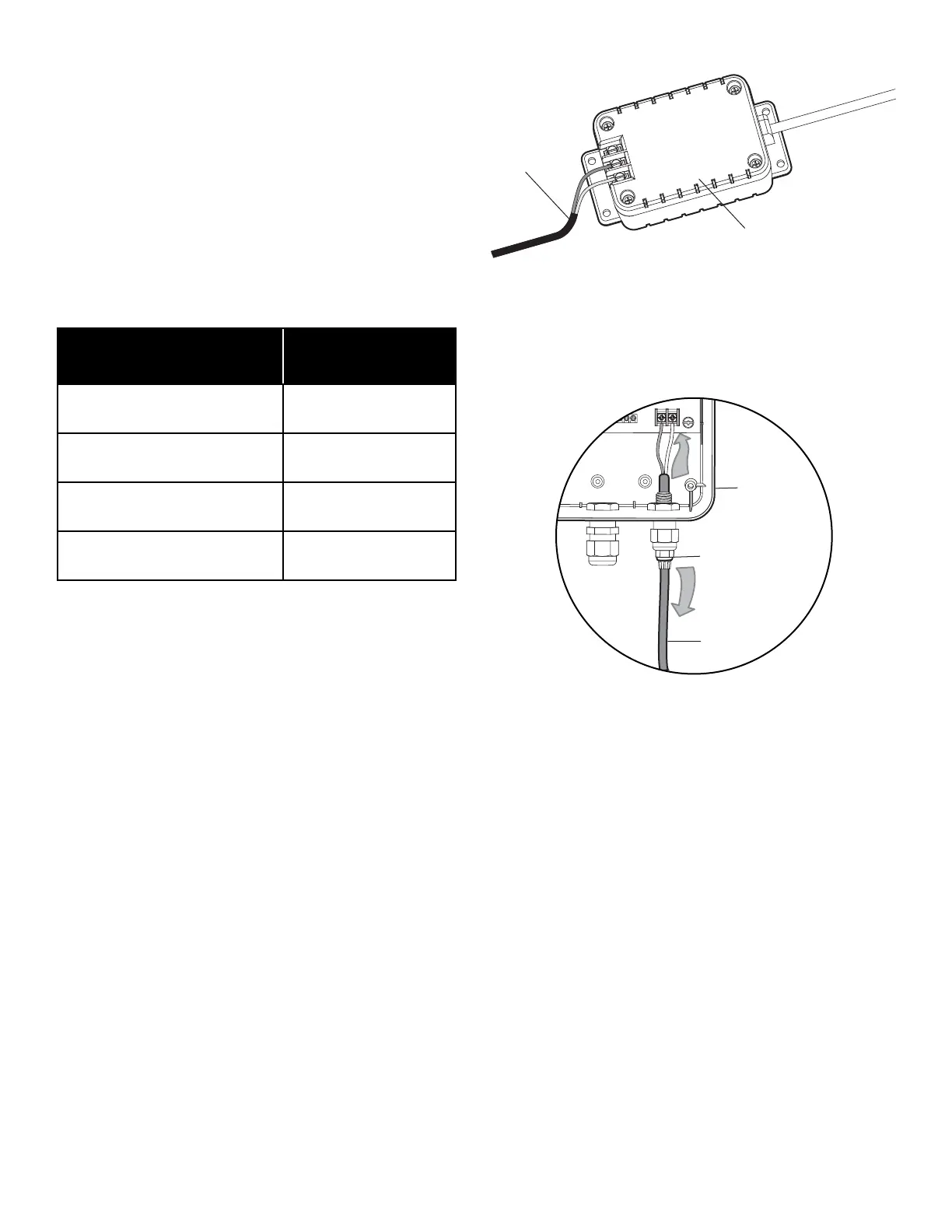
• Connect and fi rmly secure 2 conductor wires to the
terminals marked COM and 24Vac on the power supply
provided. Refer to ‘Wire Table’ for recommended wire
size and distance from the power supply and the gate
operator control box (Figure 2).
• Pull wire through one of the water tight connector nuts
located on the bottom of the control box. Tighten nut
fi rmly. Pull gently on the wire to confi rm it is secure
(Figure 3).
• Connect and fi rmly secure the wires from the power
supply to the control board terminals marked 24Vac
(Figure 3).
Power Supply
Wiring to
Control Box
Figure 3
Figure 2
* UL Listed, Stranded, Direct Burial, UV Resistant Wire
Installed per the National Electric Code, NEC.
11 Installation
Operator
Cable
Watertight
Connector Nut
Control Box
Distance from indoor AC
Outlet to Control Box
Wire Gauge Needed
100 ft. (30.5 m) or less 16 gauge
100 - 150 ft. (30.5 - 45.7 m)
14 gauge*
150 - 250 ft. (45.7 - 76.2 m)
12 gauge*
250 ft. (76.2 m) and above Not Recommended