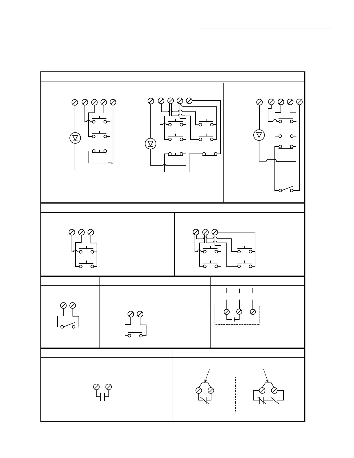
CONTROL CONNECTION DIAGRAM
IMPORTANT NOTES:
1. The 3-Button Control Station provided must be connected for operation.
2. If a STOP button is not used, a jumper must be placed between terminals 4 and 5.
3. When adding accessories, install them one at a time and test each one after it is added to ensure proper installation and operation
with the Commercial Door Operator.
3 BUTTON STATION OR 3 POSITION KEYSWITCH WITH SPRING RETURN TO CENTER AND STOP BUTTON
2 OR MORE KEY LOCKOUT
R1 R2
R3
7 6 4 5
Stop
Close
Open
Stop
Close
Open
7 6 4 5
Stop
Close
Open
2 BUTTON STATION OR 3 POSITION KEYSWITCH WITH SPRING RETURN TO CENTER
STANDARD
7 6 4
Close
Open
D1 & E2
MODE ONLY
2 OR MORE
7 6 4
Close
Open
Close
Open
D1 & E2
MODE ONLY
OPEN / CLOSE
1
4
B2, T, TS & FSTS
MODE ONLY
1 BUTTON STATION OR ANY AUXILIARY DEVICE RADIO CONTROLS
EXTERNAL
RADIO RECEIVER
NON-MONITORED EDGE SENSOR TO REVERSE OR STOP
EXTERNAL INTERLOCK
11
8
2
3
2
3
Remove Factory Installed Jumper
When Interlock is Used
ONE 2 OR MORE
STANDARD
7 6 4 5
Stop
Close
Open
All Wiring Types
Keyswitch
Edge Sensor
10
Maintenance
Alert LED
10
10
Maintenance
Alert LED
Maintenance
Alert LED
(RED)
(WHITE)
(RED)
(WHITE)
(RED)
(WHITE)
Note: 11 and 4 are both the same common.
Either is acceptable.
See note 2.
See note 2.
See note 2.
TIMER DEFEAT SWITCH
NOTE: 32 Vdc power supplied from white
and yellow wires located within the
electrical box.
NOTE: Stop circuit must be wired in series for
all stop buttons to function. This may require
removal of factory installed jumper bar in the
3-button station.
Keyswitch
11
12
(WH) (OR) (YE)
© 2018, LiftMaster
01-39130B All Rights Reserved

 Loading...