Mirror and Decrypt
Next Generation Security Gateway Guide R80.20 | 33
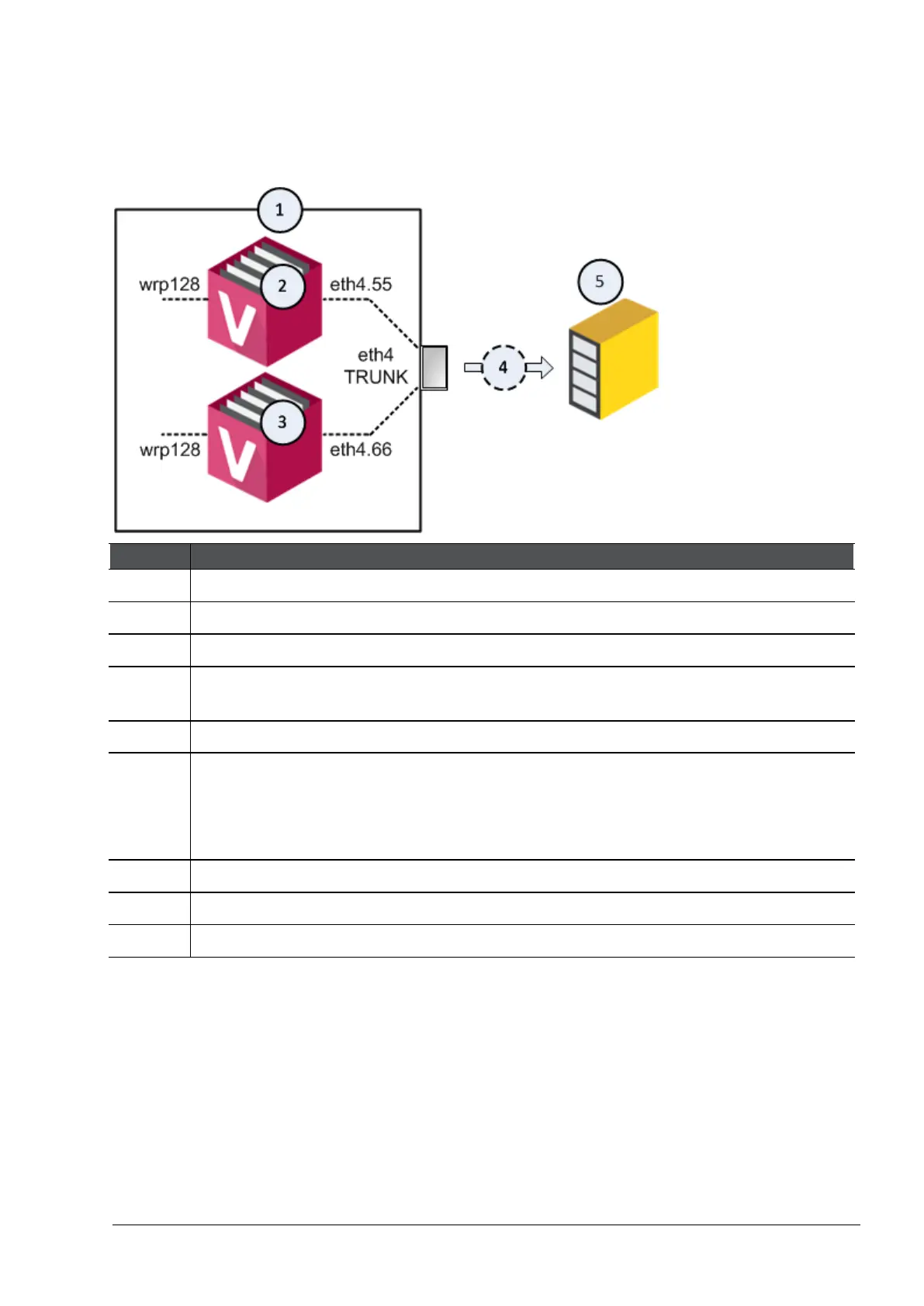
Example topology for several Virtual Systems:
Note - This topology requires you to configure a VLAN Trunk on the Recorder or Packet-Broker.
The VLAN Trunk on the Recorder or Packet-Broker must accept all VLAN IDs that you configure in
the objects of the applicable Virtual Systems in SmartConsole.
1 VSX Gateway.
2 First Virtual System, through which your networks send and receive their traffic.
3 Second Virtual System, through which your networks send and receive their traffic.
4 Flow of the decrypted and mirrored traffic from the VSX Gateway (1) to the Recorder,
or Packet-Broker (5).
5 Recorder, or Packet-Broker.
eth4 Designated physical interface on the VSX Gateway (1).
This interface is configured as VLAN Trunk in the VSX Gateway object in
SmartConsole.
Virtual Systems (2 and 3) connect to this VLAN Trunk interface with VLAN interfaces.
eth4.55 VLAN interface on the first Virtual System (2).
eth4.66 VLAN interface on the second Virtual System (3).
wrp128 One of the virtual interfaces on the Virtual Systems (2 and 3).
Important - It is not supported to change the designated physical interface with the vsx_util
change_interfaces command (for information about this command, see the
R80.20 VSX
Administration Guide
https://sc1.checkpoint.com/documents/R80.20_GA/WebAdminGuides/EN/CP_R80.20_VSX_Admin
Guide/html_frameset.htm or
R80.20 Command Line Interface Reference Guide
https://sc1.checkpoint.com/documents/R80.20_GA/WebAdminGuides/EN/CP_R80.20_CLI_Refere
nceGuide/html_frameset.htm).




 To Next Page