Do you have a question about the Chemitec 4204 and is the answer not in the manual?
Details on manual conventions, warnings, and safety notes.
Statement of manufacturer's liability regarding instrument use and safety.
Operating limits and essential safety precautions for instrument use.
Illustrations and explanations of graphic symbols used on the instrument.
Information presented on the instrument's identification plate.
Guidelines for recycling and reusing instrument materials and components.
Key features and capabilities of the flow meter unit.
Detailed overview of the instrument's hardware components and specifications.
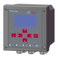
Identification and description of the unit's front panel controls and indicators.
List of components included in the instrument package.
Instructions for mounting the device on a wall.
Instructions for installing the unit in a 144x144 electrical panel.
Diagrams and descriptions of terminal board connections for plant integration.
Guidelines for safely connecting the instrument to the power supply.
Procedures for connecting the unit to external systems and utilities.
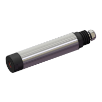
Recommendations for correctly positioning and installing the measurement probe.
Overview of how system information is displayed in various operating modes.
Initial startup procedure, system initialisation, and parameter loading.
Procedure for selecting functions and inputting necessary parametric values.
Basic settings for operating logic, including relays, system setup, and flow parameters.
Configuration of relay operations, including pulse and alarm settings.
Alarm configuration for probe connection loss and eco signal issues.
System configuration for date/time, communications, language, password, and display.
Parameter settings for fluid level measurement, including units and probe distance.
Parameters for instant flow measurement, including units, decimals, and device types.
Configuration for empirical flow calculation using a table of points.
Specific setup for Bazin type overflow flow measurement.
Procedure for resetting setup parameters to default values.
Manual testing of level, relays, and analog outputs for diagnostics.
Configuration of analogue outputs for flow and temperature measurements.
Functions for displaying and managing data archives for totalizer and flow.
Procedure for exiting programming mode and saving or discarding settings.
Registers for firmware version and device ID.
Registers for recorded values like level, temperature, and distance.
Registers related to relay operation times and total commutations.
Registers for tracking alarms and their codes.
Information on downloading data via Modbus, including query, response, and session management.
Steps for requesting service and troubleshooting the instrument.
Contact information for CHEMITEC offices and service centers.
| Brand | Chemitec |
|---|---|
| Model | 4204 |
| Category | Measuring Instruments |
| Language | English |