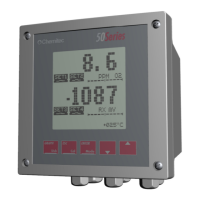
4204
FLOW METER
TECHNICAL MANUAL P/N XXX-0000 Rev. 5 Ver. 3.4
4
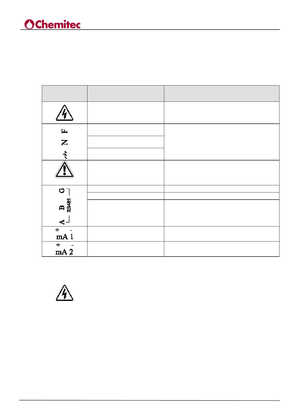
1.4 GRAPHIC SIGNS
The following Table 1-1 indicates the drawings, relative descriptions and position of all the graphic
signs placed on the instrument panel and on any other external instruments or devices to which it
can be connected.
Table 1-1 Graphic signs
SIGN DESIGNATION POSITION
Danger sign
Sign placed near the terminals for the connection
to line voltage (See Paragraph 1.4.1)
Phase
Signs placed near the connections of the
instrument to the power supply line (See Paragraph
3.1.1)
Neutral
Grounding protection
Caution! Consult the attached
documentation
Symbol positioned in correspondence with the
points in the manual that require special attention
Positive
Positive pole of the connector RS485
Negative
Negative pole of the connector RS485
Terminal
Sign placed near the cable shielding for RS485
Analogue output no. 1
0/4 ÷20mA galvanic separation
Analogue output no. 2
0/4 ÷20mA galvanic separation
1.4.1 DANGER SIGN
The sign indicates DANGER for the operator. It is placed inside the instrument near the
points where the voltages present may be dangerous.
We recommend paying maximum attention.
Especially when the sign, placed near the cable connections to peripherals, refers to the attentive
reading of the user manual for a correct and safe connection.