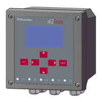
4204
FLOW METER
TECHNICAL MANUAL P/N XXX-0000 Rev. 5 Ver. 3.4
29
“FIXED” it remains constantly active
“AUTO” it is activated when any test is pressed and is disabled after more than 15 seconds
if none of the keys are touched.
7.2.3 LEVEL [1.3]
This segment of the programme allows for the calculation System to acquire the parameters related
to positioning of the probe, with reference to the level (recess) of the fluid.
Move to “SETUP” [1.0] and select “LEVEL” [1.3](See Fig. 7.3).
The programme has two items, which are:
“GENERAL” [1.31]
“PARAMETER” [1.32]
7.2.3.1 Level Param[1.31]
This segment of the programme sets the metric units of measurement used for all remote
measurements.
Move to “LEVEL” [1.3]; select “GENERAL” [1.31]
Using the function “UNITS” the operator can ask the programme to represent the data in:
“M”
“cm”
“mm”
The ratio is created according to the contents of paragraph 7.1 i).
Using the function “DECIMAL”, the operator can define the number of decimals that follow the
unit. The maximum value that can be set is “3”.
It is important to remember that the maximum value set is a function of the unit of measurement.
The programme operates internally on a reference in "mm", therefore the maximum number of
decimals permitted is:
UNITS DECIMAL
m 3
cm 1
mm 0
7.2.3.2 Parameters [1.32]
Using the functions, the following should be inserted into the programme:
• the height of the probe compared with the corresponding point for flow"0"
For spout applications, the distance will be between the "face" of the transducer and the spout
threshold
For Venturi channel applications or similar, the distance will be between the "face" of the
transducer and the bottom of the channel.
• the maximum height of the water channel (hydraulic recess) at the maximum flow, compared
with point zero. ( This value should be calculated using the specific formula for the type of spout
or channel used)
Move to “LEVEL”[1.3]and select “PARAMETERS” [1.32]
The items that can be inserted are:
“h0 DIST”
“h. MAX”
 Loading...