4204
FLOW METER
TECHNICAL MANUAL P/N XXX-0000 Rev. 5 Ver. 3.4
12
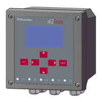
3.1.3 TERMINAL BOARD CONNECTIONS
The terminal board connections and the definitions of the Unit connections to the plant to be placed
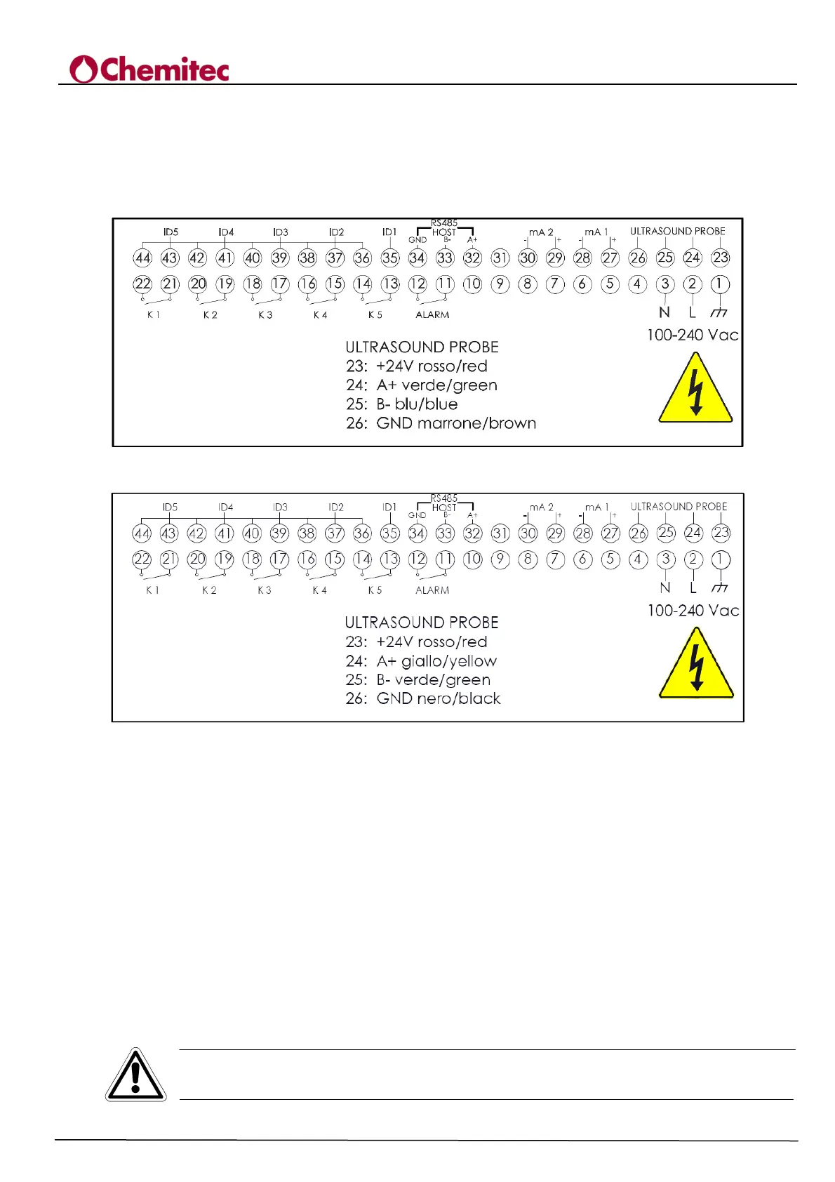
under control are shown in Figure 3-2 and 3-3 (depending by the connected probe).
It shows the connections diagram viewable on the cover of the connections housing.
Figure 3-2 Electric connections for S425
Figure 3-3 Electric connections for S425/C
3.2 CONNECTING POWER SUPPLY LINE
If all possible make sure that there aren’t any cables assigned to the controls of other power drawing
equipments near the unit or on the same path of the connecting cable, which could create inductive
interferences for the instrument.
As much as possible, apply to the instrument stabilised power voltage according to the information
on the plate.
Absolutely avoid connecting the instrument to indirect/ reconstructed power supplies, for example,
through the use of transformers, where this reconstructed power goes to supply other systems
besides the unit (i.e.: inductive type), because this procedures generate high voltage spikes which
once they are radiated it’s difficult to block and/or eliminate them.
CAUTION
The electric line must be fitted with an appropriate circuit breaker and magnetothermic
switch, in compliance with good rules of installation
 Loading...