Chemtrac Systems, Inc.
Page 12
SECTION 2.0 MOUNTING AND INSTALLATION
2.1 MOUNTING LOCATION
The sensor can be located several hundred feet from the monitor. The sensor must be
mounted in a vertical position with the sample flowing into the inlet (3/4” barb fitting) and
exiting from the outlet (PVC elbow). Typically, the sensor is mounted as closely as
possible to the sampling point. Minimizing sample line lengths provides quicker
response to process changes. Sample may be obtained by using a sample pump,
tapping off a pressurized line, or using gravity feed system to get sample to the sensor.
The sample flow rate should not exceed 5.0 GPM for Dura-Trac sensor and 10.0 GPM
for Dura-Trac II sensor. Draining to atmosphere (unobstructed) is required; a
closed pipe (pressurized) drain is not recommended.
The Monitor/Controller module should be installed in a location, which will allow regular
viewing of the display as well as easy access to the front panel menu keys. See
Mounting Dimension Diagrams at end of Manual.
2.2 POWER REQUIREMENT
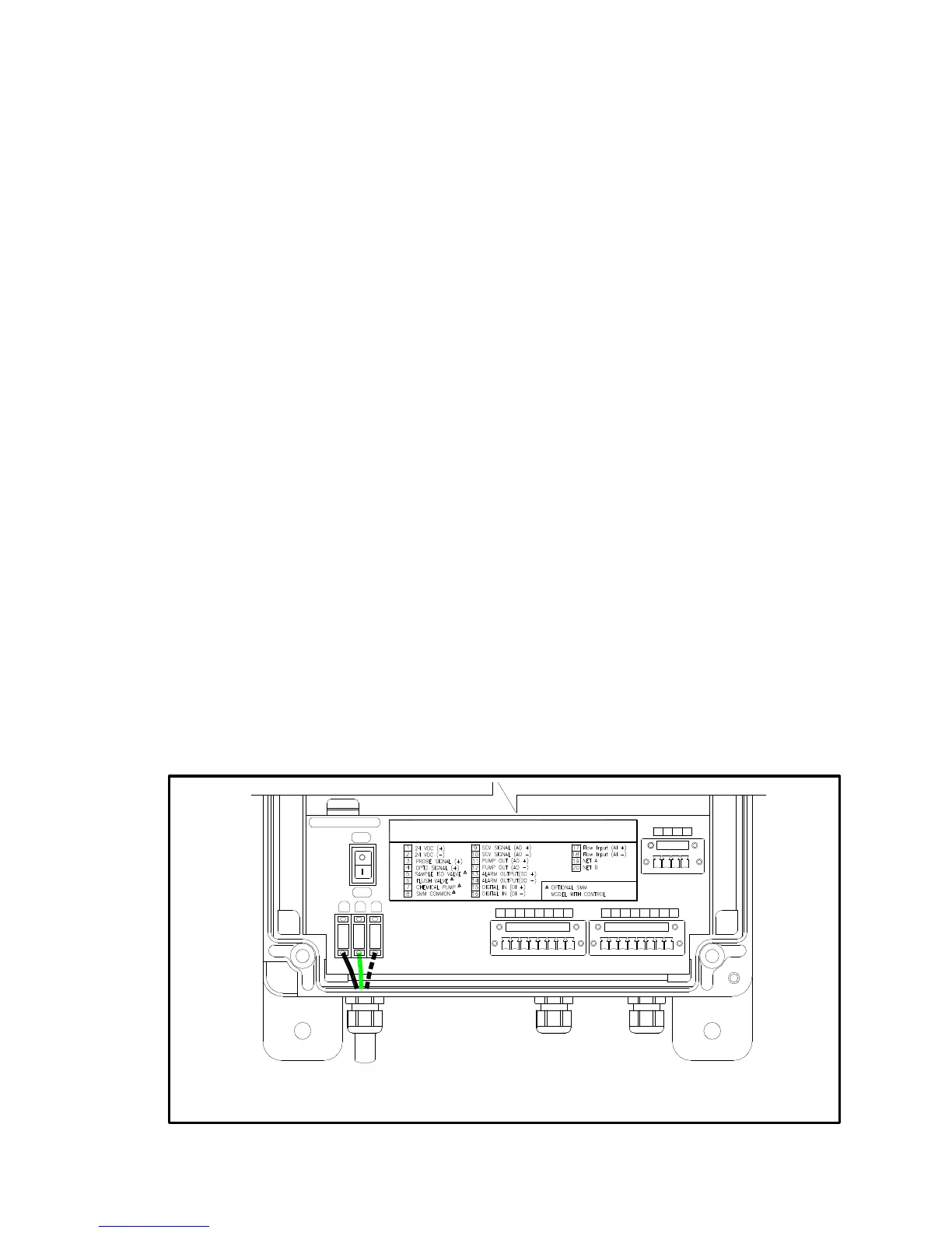
Electrical power should be connected in the following order
R Insert the ground wire into the middle terminal labeled “G”.
R Insert the hot wire into the left terminal labeled “L”.
R Insert the neutral wire into the right terminal labeled “N”.
For safety and proper operation, the monitor must be properly grounded through their
power cord. In cases where potential noise sources could affect the performance of the
equipment, a "surge suppressor" must be installed with the unit. The following drawings
show power terminal connections for models SCM2500XRD and SCC3500XRD
monitors, and Dura-Trac or Dura-Trac II Sensor.
Figures 3 thru 5 illustrate power-wiring connections to Monitor/Controller, Dura-Trac,
and Dura-Trac II Sensors.
8 9 1311 12 1514 16
18
17
19 20
10
FIELD WIRING TERMINALS
POWER CORD
OFF
G
GND
L
L N
N
ON
FUSE: AGC-1.5A
FUSE
1
WARNING TURN POWER OFF BEFORE MAKING ANY WIRE CONNECTIONS
TO AVOID DAMAGING THE ELECTRONIC CIRCUIT.
SMM | Sensor
7
*
*
432 65
*
*
*
FIGURE 3. Monitor/Controller Power Wiring

 Loading...