Chemtrac Systems, Inc.
Page 14
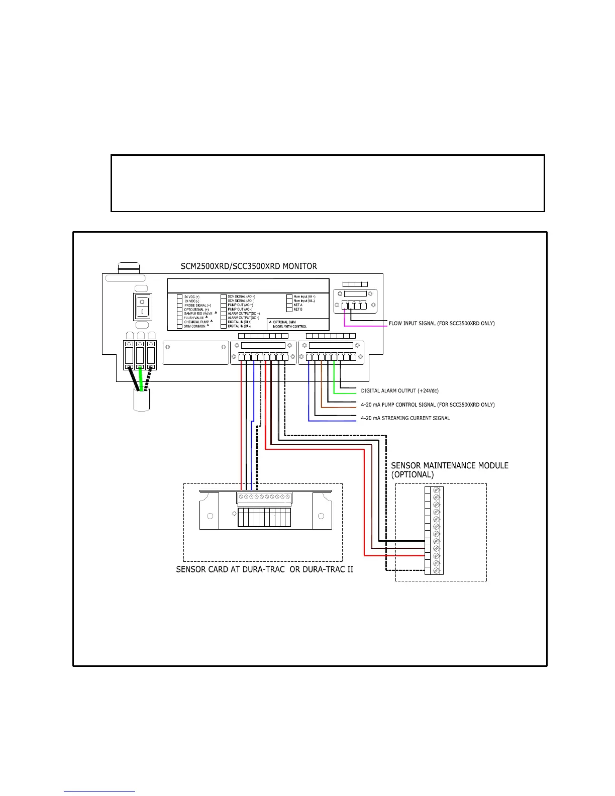
2.3 SIGNAL WIRING
The Dura-Trac and Dura-Trac II Sensors transmit the sensing signal to
Monitor/Controller by a multi conductor wires, see Figure 7 for signal wires
interconnection diagram. Twisted shielded cable should be used. The cable should be
enclosed in conduit for maximum protection against damage or electrical interference.
Do not run cable in same conduit with any other wiring.
CAUTIONS
R Make sure the monitor’s power switch is turn to off position before making any
signal wiring connections.
(BLACK)
+24 Vdc
1
(RED)
Opto (W)
10
Shield
Signal +
Signal -
Vdc Gnd
5432
Opto (O)
- Probe
+ Probe
Opto (B)
6 87 9
(WHITE)
(BLUE)
WARNING TURN POWER OFF BEFORE MAKING ANY WIRE CONNECTIONS
TO AVOID DAMAGING THE ELECTRONIC CIRCUIT.
3
SMM | Sensor
4
6
5
7
8
1
2
11
14
13
12
15
16
1
9
10
*
*
*
*
32 4
*
86
5
7
19
9
20
121110
17
18
(BROWN)
(WHITE)
(BLACK)
(RED)
CHEMICAL PUMP
SAMPLE ISO VALVE
24 VDC COMMON
FLUSH VALVE
64 5321 12111087 9
16151413
1817 19 20
FUSE: AGC-1.5A
GND
L
N
ON
GL N
OFF
FUSE
FIGURE 6. Signal Wires Interconnection Diagram
 Loading...