Chemtrac Systems, Inc.
Page 6
SECTION 1.0 GENERAL INFORMATION
1.1 DESCRIPTION OF OPERATION
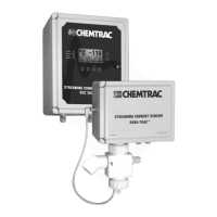
The Streaming Current Monitor/Controller includes a remote sensor module placed at
the desired sample point, and a Monitor/Controller module. The monitor is a charge-
measuring device. The charge that it measures is the net ionic and colloidal surface
charge (positive and negative) in the sample being tested. Streaming current is related
to zeta potential, however, they are not the same value.
The treated water sample flows into the sample cell where it is drawn into the bore
during the upstroke of the piston cycle and is expelled from the bore on the piston down
stroke. Particles contained in the water are temporarily immobilized on the piston and
cylinder surfaces. As the water is moved back and forth by the piston, charges
surrounding these particles (+ and -) are moved downstream to the electrodes. This
movement of like charges causes an alternating current to be generated, defined as
"streaming current." A signal gain selector, accessed through the menu screen, is used
to select the best signal amplification. The signal amplification should be set where a
normal change in dosage results in a desired deviation in streaming current (normally 30
units). The displayed streaming current value (SCV) should be considered as a relative
reading due to amplification of the primary signal.
The streaming current amplitude and polarity is a function of sampling location in the
treatment process. It is important to understand why the streaming current varies at
different points in the system to properly interpret the readings, therefore, Section 1.2
should be read very carefully.
1.2 SELECTING PROPER SAMPLE POINT
The sample must be taken at a point where uniform distribution and mixing of coagulant
is obtained for all flow rate conditions, and at a point that allows for a quick response to
chemical feed changes as measured by the monitor (i.e. after the rapid mixer or static
mixer, and before the slow mixer or flocculation basin). The lag time, or the amount of
time it takes the water to travel from the point of chemical addition to the sensor, should
be no greater than 3 minutes (30 seconds to 1.5 minutes are typical lag times). If
uniform distribution and mixing is not being obtained at a selected sample point, the
streaming current reading will oscillate. If the chemical is not being properly mixed
(indicated by an oscillating monitor reading), the sample point needs to be moved
further downstream away from the mixing device to allow the chemical more time to mix
in with the water. Under rare circumstances, moving the sample point further
downstream in order to obtain a more stable reading may result in a lag time longer than
3 minutes. Steps should be taken to improve chemical mixing under these conditions.
When possible, avoid sampling from places where sludge, grit, etc., will be drawn into
the sensor sample cell. Sample lines must be sized to provide velocities that will
prevent floc/sludge accumulation. Keep sample lines as short as possible to minimize
delay in response time.
Figure 1, Streaming Current Profile, normally observed in a typical water plant. When
coagulant is added to raw water, the charge neutralization process begins immediately.
The time required for this neutralization process to go to completion is primarily a
function of mixing, time, raw water characteristics, type of coagulant, and to a lesser

 Loading...