Model 108 FLEX-AUGER Installation Manual
IMPORTANT: Stretch the auger 8 inches (200 mm) for every 50 feet
(15.2 m) of length. Example: For a 150 ft. (45 m) system the auger
should be cut 24 inches (610 mm) shorter than its natural length. Mea-
sure the amount of stretch from the rear edge of the boot and cut the
auger at that point.
6. Figure 16 shows the proper assembly of the Model 108 boot compo-
nents. Insert the Anchor Shaft into the auger until the auger touches
the anchor flange. The auger must be threaded onto the Boot An-
chor Assembly, through the clamp pin. Use a 5/16" open-end
wrench to tighten the clamp pin setscrew on the auger.
7. CAREFULLY remove the locking pliers while holding on to the
Anchor and Bearing Assembly and auger securely.
8. CAREFULLY allow auger to draw the Anchor and Bearing As-
sembly back into the Lower Boot. DO NOT ALLOW THE BEARING
TO BE SLAMMED BACK INTO THE BOOT.
9. Attach the Anchor and Bearing Assembly to the Boot, using tube
clamp provided.
10. Place the cannonball in the boot.
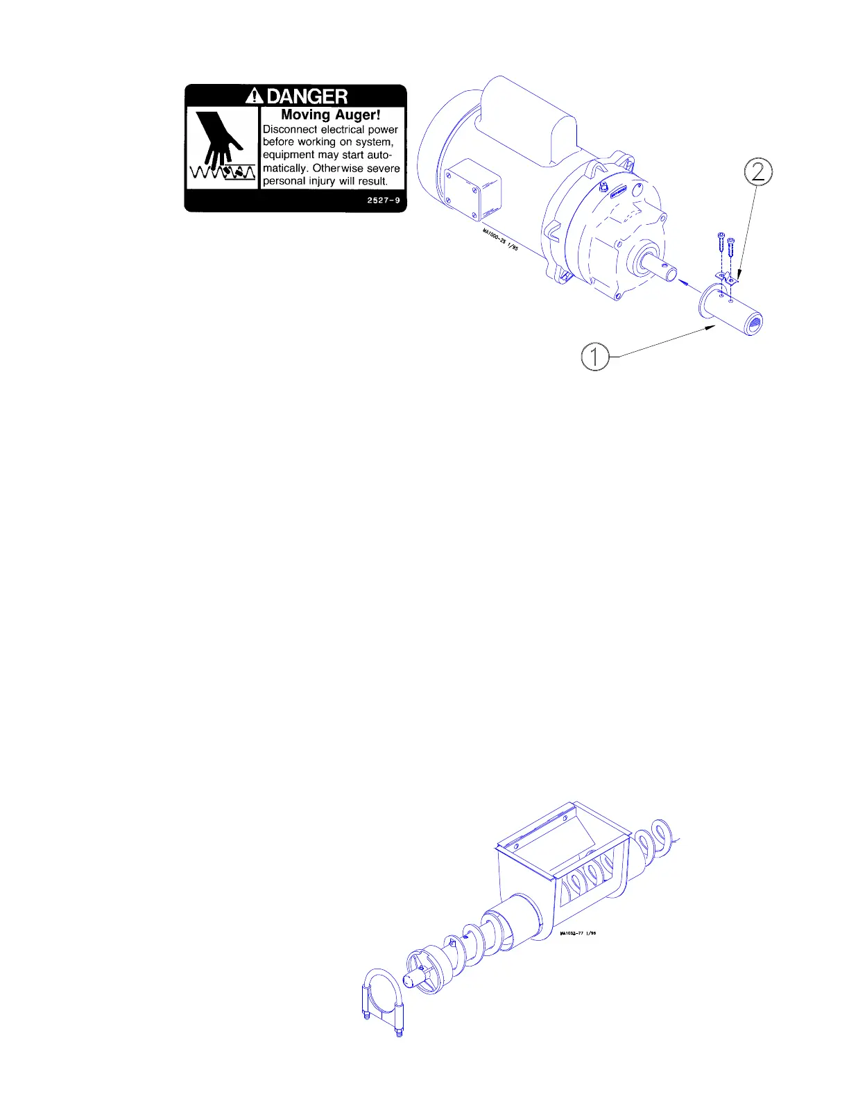
Figure 15. Model 108 Auger Installation (Drive End)
Key Description
1 Model 108 Driver Assembly
2 Anchor Clamp
Figure 16. Model 108 Anchor and Bearing Installation.
 Loading...

