Model 108 FLEX-AUGER Installation Manual
Typical System Installations
The FLEX-AUGER Delivery Systems may be readily adapted to
most feed delivery applications. The systems illustrated on the
following pages show the most common types of FLEX-AUGER
installations. These diagrams provide guidelines for laying out your
system.
Four systems that are NOT recommended are shown on Pages 12
and 13. Possible alternate systems are provided with each
non-recommended system.
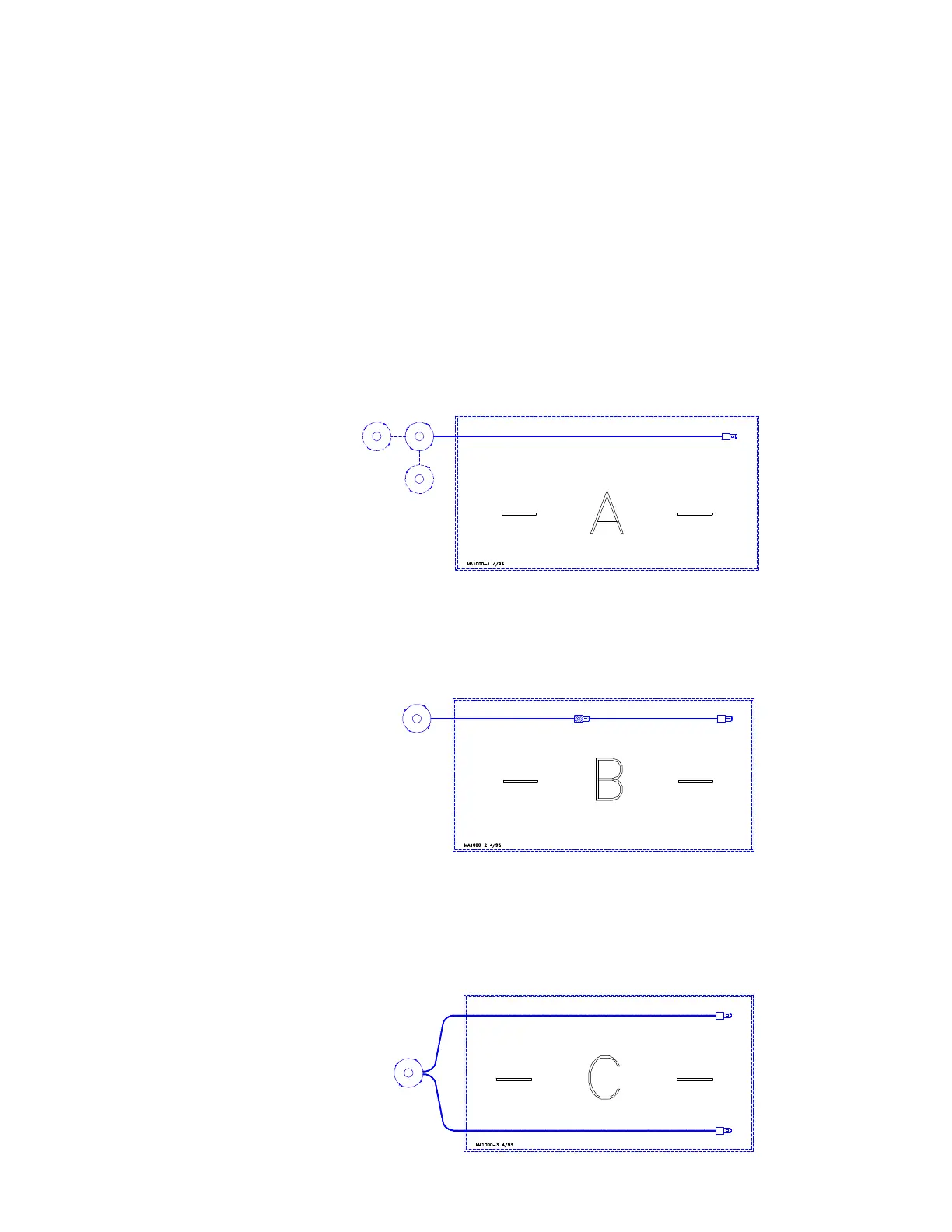
System A represents a typical straight-line system with optional
tandem bin set-up. If this were a long system with many outlet
drops, some feed bypass should be provided by increasing the size
of the outlet holes, from small at the bin end, to the large at the
control end of the line.
System B represents an extended length system. Equalize the
power requirements of each part of the system. Optional equipment
required.
System C represents a twin boot system with the feed bin centered
at one end of the building.
 Loading...

