Model 108 FLEX-AUGER Installation Manual
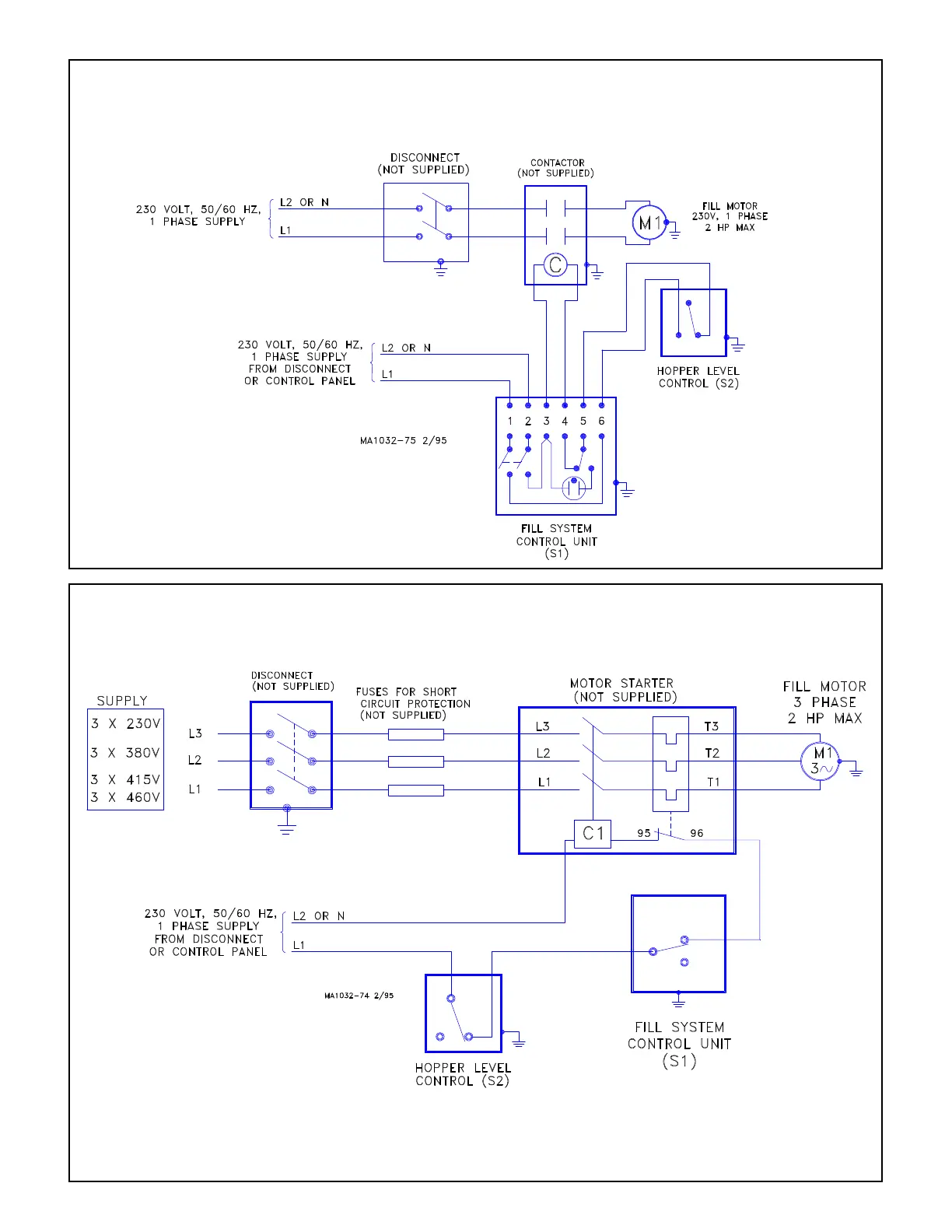
Wiring Diagram for
Model 108 Systems using a Hopper Level Control (Three Phase)
Important: If an Agri-Time Time
Clock is to be used, refer to MA1061
Instruction for control wiring.
If an Auger Timer is to be used, re-
fer to MA951 Instruction for control
wiring.
Important: If system is to be controlled by a Proximity Drop
Tube Switch, refer to MA1044 Instruction for switch wiring.
If the system is to be controlled by a mechanical Drop Tube
Switch, refer to MA1099 Instruction for switch wiring.
Wiring Diagram for
Model 108 Systems using a Hopper Level Control
(1-1/2 H.P. or larger - Three Phase)
Important: If an Agri-Time Time
Clock is to be used, refer to MA1061
Instruction for control wiring.
If an Auger Timer is to be used, re-
fer to MA951 Instruction for control
wiring.
Important: If system is to be
controlled by a Proximity Drop
Tube Switch, refer to MA1044
Instruction for switch wiring.
If the system is to be con-
trolled by a mechanical Drop
Tube Switch, refer to MA1099
Instruction for switch wiring.
 Loading...

