Installation
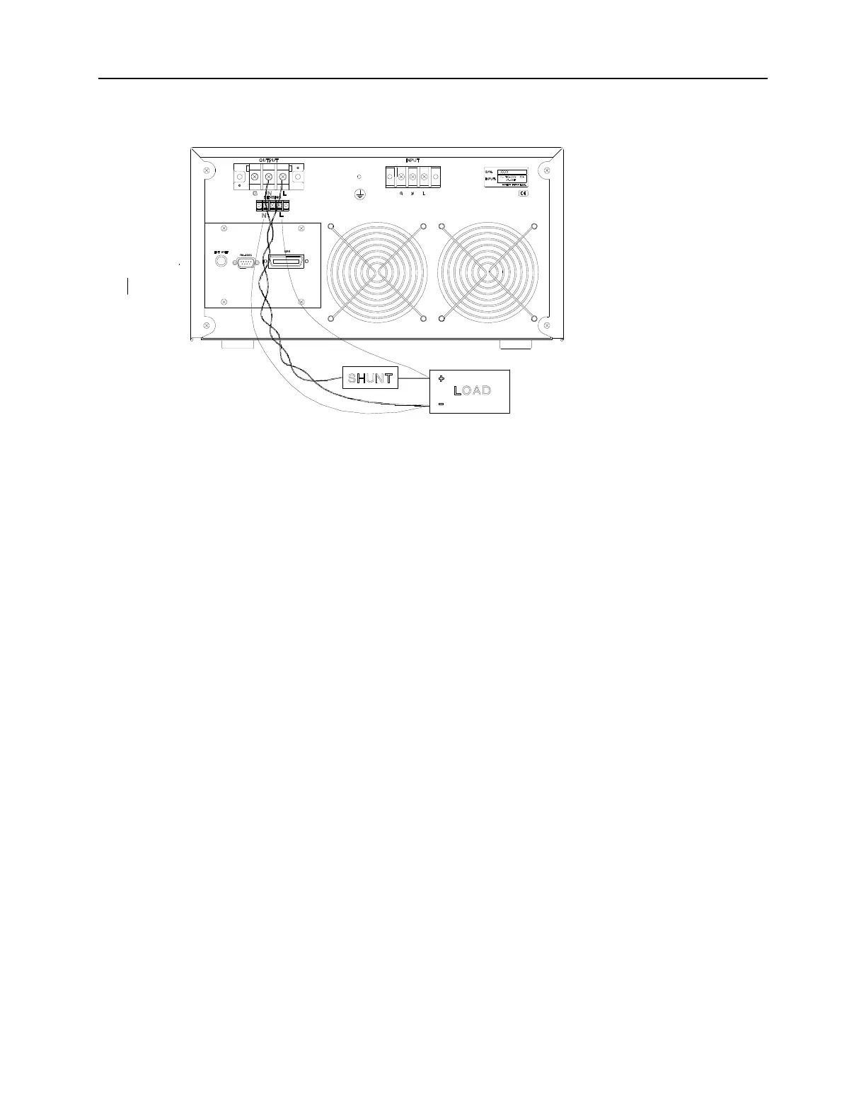
Figure 2-2 Output Connection
2.5 Remote Sense Connection
The remote sensing connection improves the voltage regulation by monitoring the voltage at the
load, not at the AC source output terminal. Remote sensing allows the power supply to increase
the output voltage automatically, and compensate for the voltage drops in the load leads. Note
that with remote sensing, voltage read-back is at the load.
The instrument can be managed for remote voltage sensing by connecting the load leads from the
output terminals to the load, and the sensing leads from the terminals L and N to the load as
shown in figure 2-2.
2.6 Power-on Procedures
Apply the line power to the input terminals, and turn on the power switch on the front panel.
No load shall be connected to the output terminal block. The instrument will do a series of self-
tests whenever the user turns on the power switch. All LEDs on the front panel, including
alphanumeric and indicator LEDs, are lighted for three seconds or so. Then, the seven-segment
LEDs and alphanumeric LEDs will display “SELF TEST”. It means that the 6430, 6420 or
6415 is running a self-test.
Shortly afterwards, the seven-segment LEDs will display the model number like 6430, 6420 or
2-3