Programmable AC Source 6430/6420/6415 User‘s Manual
1.4 Operational Panels
1.4.1 Front Panel
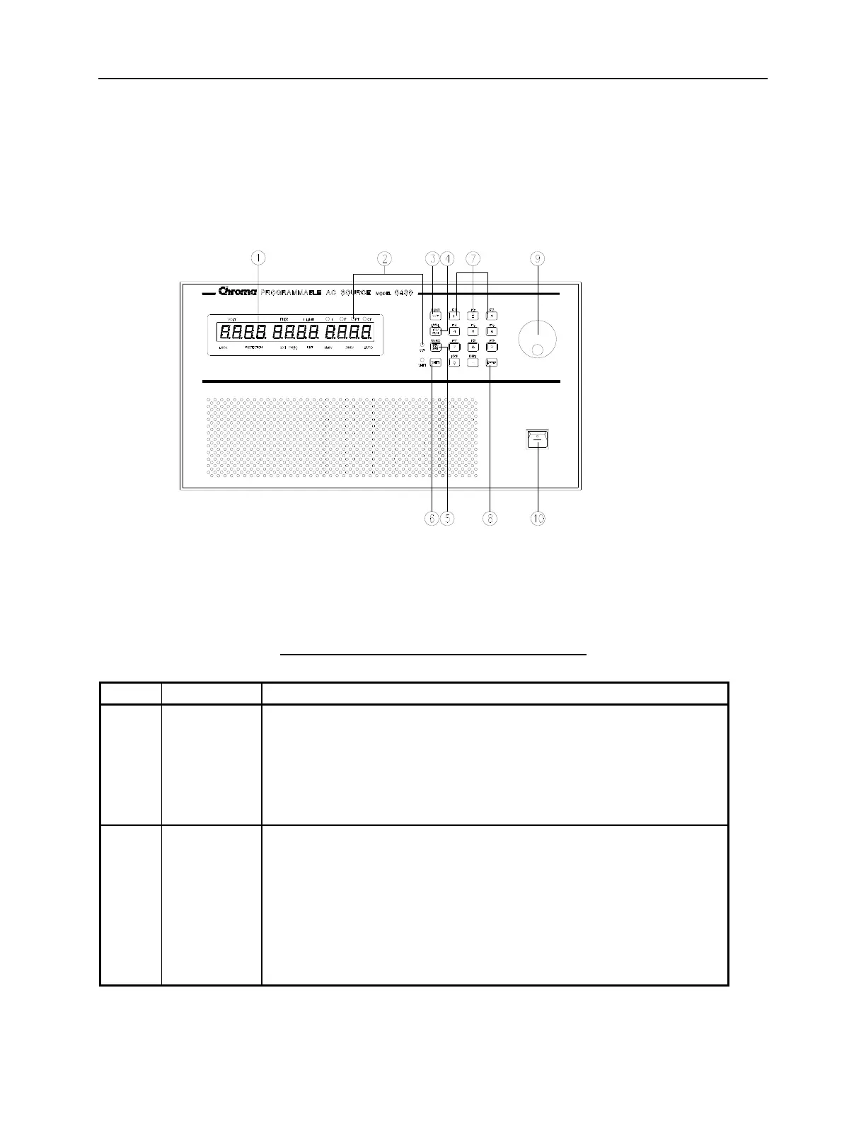
Figure 1-1 Front Panel
Table 1-1 The Description of the Front Panel
Item Symbol Description
1
Alphanumeric LED: A row of red seven-segment LEDs are
equipped for displaying setup messages and numeric value of
settings, or measurement results. The display area is divided into
three sections: value of V shown on the left, frequency or I limit
in the middle, and any of I/P/PF/CF measurement value on the
right.
2
Indicator LED: LEDs located on the upper and lower part of the
display panel are the indicators showing the activated status.
These indicators include “VOLT”, “FREQ”, “I LIMIT”, “I”, “P”,
“PF”, “CF”, “LOCK”, “PROTECTION”, “EXT PROG”, “RMT”,
“150V”, “300V”, “AUTO”.
Besides, two LEDs, “OUT” and “SHIFT” for showing activation
of output and shift mode, are located on the keypad area next to
the corresponding keys.
1-4