Do you have a question about the Chroma 69200-1 and is the answer not in the manual?
Provides a general introduction to the 69200-1 Charge/Discharge Controller and its naming convention.
Details the operational modes, output capabilities, and input specifications of the controller.
Outlines the technical specifications of the 69200-1 controller, highlighting its role.
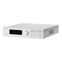
Describes the function keys and their locations on the front and rear panels of the device.
Guides users through the initial inspection process after unpacking the instrument and handling transit damage.
Provides essential preparation steps before operating the device, including environmental and connection checks.
Details the necessary input voltage, frequency, current, and power ratings for the device.
Explains how to connect the output ports for communication with other devices.
Provides instructions on how to assemble the racket kit and handle for the instrument.
Outlines the step-by-step procedure for powering on the instrument safely.
Offers guidance on proper maintenance and cleaning procedures for the instrument's longevity.
Specifies the recommended environmental conditions for operating the instrument.
Introduces the local operation mode and how to input test data using the front panel.
Explains the layout and function of the device's operating interface and keys.
Details the various operating screens, modes, and settings available on the controller.
Guides on setting up the SCPI communication method for remote control operations.
Lists and describes the SCPI commands available for controlling the 69200-1.
Details the specific SCPI commands and settings for CC Discharge mode operation.
Details the specific SCPI commands and settings for CV Discharge mode operation.
Details the specific SCPI commands and settings for CP Discharge mode operation.
Details the specific SCPI commands and settings for CC Charge mode operation.
Details the specific SCPI commands and settings for CV Charge mode operation.
Details the specific SCPI commands and settings for CP Charge mode operation.
Explains how to set and load battery simulator curves for various parameters.
Provides an overview of remote control capabilities via Ethernet for the 69200-1.
Guides on setting up Ethernet remote control, including IP addressing and network interface usage.
Details how to manually set IP, Subnet Mask, and Gateway for PC connection.
Explains how to confirm the successful setup of the local area network connection.
Describes how to perform a preliminary voltage calibration check using a DC source.
Details how to perform a preliminary current calibration check using a DC source.
Provides an overview of the 69200-1 as a data collector and its internal components.
Details the different parts of the 69200-1 system, including boards and auxiliary power.
| Model | 69200-1 |
|---|---|
| Power Supply | AC |
| Communication Interface | USB, GPIB |
| Input Voltage | 200-240 VAC |
| Input Frequency | 50/60 Hz |