19
INSTALLATION MANUAL PRORAPID |
Before working on the unit, switch o the power supply and secure it against
being switched on again! Check that there is no power owing! Electrical
connections may only be made by a specialist and in compliance with the
applicable regulations. The unit may not be put into operation if there is
visible damage to the housing, e.g. cracks.
The unit may not be accessible from behind.
Low-voltage cables such as temperature sensor cables must be routed
separately from mains voltage cables. Feed temperature sensor cables only
into the left-hand side of the unit, and mains voltage cables only into the
right-hand side.
The customer must provide an all-pole disconnecting device, e.g. an
emergency heating switch.
The cables being connected to the unit must not be stripped by more than 55
mm, and the cable jacket must reach into the housing just to the other side of
the strain relief.
Installing the Temperature Sensors
The controller operates with Pt1000
temperature sensors which are accurate
to 1 °C, ensuring optimal control of system
functions.
!
If desired, the sensor cables
can be extended to a
maximum of 30 m using a
cable with a cross-section
of at least 0.75 mm².
Ensure there is no contact
resistance! Position the
sensor precisely in the area
to be measured! Only use
immersion, pipe-mounted
or at-mounted sensors
suitable for the specic
area of application with the
appropriate permissible
temperature range.
Low-voltage cables such as
temperature sensor cables
must be routed separately
from mains voltage cables.
Feed temperature sensor
cables only into the left-
hand side of the unit, and
mains voltage cables only
into the right-hand side.
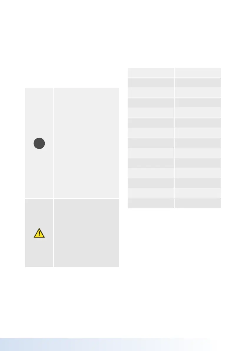
Temperature Resistance Table for
Pt1000 Sensors
°C Ω
-20 922
-10 961
0 1000
10 1039
20 1077
30 1116
40 1155
50 1194
60 1232
70 1270
80 1308
90 1347
100 1385