it measures the total current of all the loads, including also the compensation capacitor bank
(see
Figure 3)
The CT should be installed preferably in phase L1, while the voltage measuring terminals of
ComputerMAXshouldbeconnectedtophasesL2andL3(seeschematicsin
Figure 4 and Fig-
ure 5
). It’s important to respect the connection senses of P1-P2 and S1-S2 shown in the above
mentionedgs,otherwisethephasedifferencewillhavetobecorrectedbyadjustingthedevice
according to set-up procedure indicated in “6.1.8.- U, I PHASE ANGLE SETTING.”.
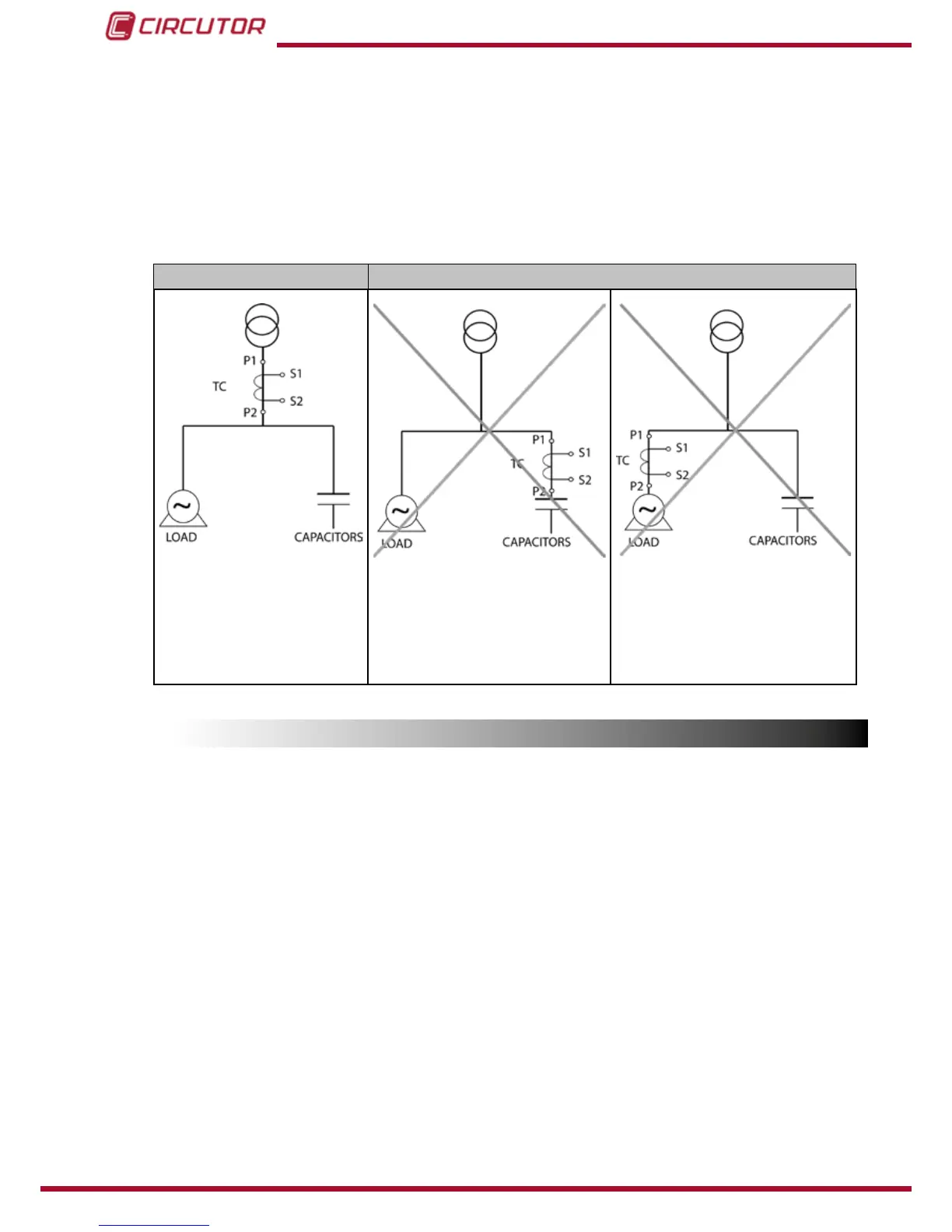
RIGHT CONNECTION WRONG CONNECTION
The CT measures the whole
current of loads + capacitor
bank.
In case of malfunction check
that the CT is not shortcircuited
If CT is placed in this position,
NONE of the CAPACITOR STAGES
WILL CONNECT.
The equipment does not regulate
properly�
If CT is placed in this position ALL
THE CAPACITOR STAGES WILL
CONNECT.
WARNING! This situation may
cause overcompensation, reso-
nance and overcurrent
Figure 3:Placement of current transformer (CT)
4.3.-CABLINGCROSSSECTIONSANDPROTECTIONS
The supply circuit must be protected by means of fuses or a circuit breaker sized between 0,5
and 2 A.
Recommendedfusesaregltype(IEC269)orMtype(IEC127).Amaincircuitbreakermustbe
providedinordertoallowthedisconnectionofcontrolcircuitsfromsupply(Computer,relays,
contactor coils, etc.)
The main switch must be easily accessible. The cabling cross section must be minimum 1,5
mm
2
for the voltage supply and for the relay outputs and 2,5 mm
2
for the cables connecting
secondary of CT to computer MAX. For distances between CT and computer higher than 10m
the cross section of the last must be increased at a rate of 1 extra mm
2
every 10 m.