4.4.-SCHEMATICS
4�4�1�- COMPUTER MAX 6
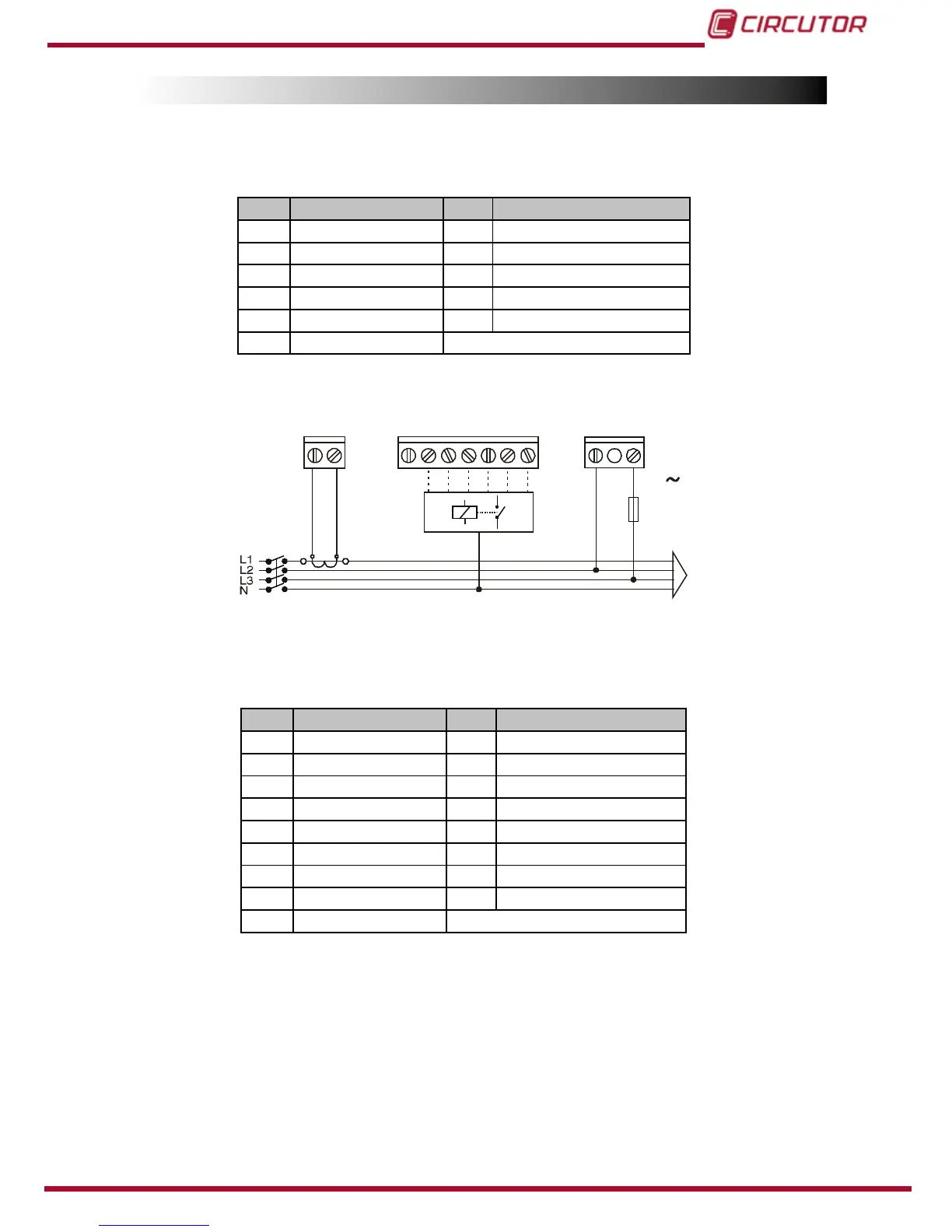
Table 4: Computer MAX 6 terminals�
Nr Description Nr Description
A Current input S1 4 RelayOutput4
B Current input S2 5 Relay Output 5
COM Relays common 6 Relay Output 6
1 Relay Output 1 C Supply/Measure input 0 V
2 Relay Output 2 D Supply/Measure input
(1)
3 RelayOutput3
(1)
Rated voltage depending on type. See device label
Figure 4: Computer MAX 6�
4�4�2�- COMPUTER MAX 12
Table 5:Computer MAX 12 terminals�
Nr Description Nr Description
A Current input S1 7 Relay Output 7
B Current input S2 8 Relay Output 8
COM Relays common 9 Relay Output 9
1 Relay Output 1 10 Relay Output 10
2 Relay Output 2 11 Relay Output 11
3 RelayOutput3 12 Relay Output 12
4 RelayOutput4 C Supply/Measure input 0 V
5 Relay Output 5 D Supply/Measure input
(1)
6 Relay Output 6
(1)
Rated voltage depending on type. See device label