5�- OPERATION
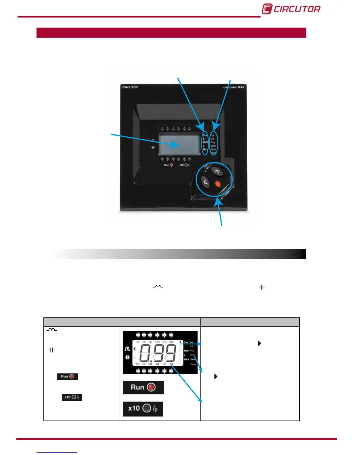
The PF regulator’s front panel shows the following items:
Navigation keys
Display
Measured
parameters
Congurable
parameters
Figure 6: computer MAX description�
5.1.- DISPLAY SCREEN
computer MAXdevicesareequippedwitha3digitsx7segmentsLCDscreen.Thescreenhas
also a set of icons, which provide information about the regulator status. The main indications
are:cosφvalue,reactivepowersign(
for lagging or inductive PF and for leading or
capacitivePF),connectedstagesandmeasurementofdifferentparameters(see “5.2.- MEA-
SURED PARAMETERS”
)
Table 6: Display screen�
Icons Screen and LEDs Icons indications
Lagging or inductive power
indication
Leading or capacitive power
indication
The LED(red)isON
in normal working conditions
The LED shows
that the reading of current or
MAX. current has to be multi-
plied by 10
In normal working conditions, RUN
LED(red)isONand
cursor points
totheparameterbeingdisplayed(Left
column list)
In SET-UP mode, the RUN LED is OFF,
the cursor is blinking and pointing to
theparameterbeingcongured(Right
column list).
Symbols indicating the stages which
areconnected(onlyinRUNmode)