7�- RUN STATUS
OncethedevicehasbeenconguredaccordingtoinstallationneedsitcanbesettoRUNmode
to regulate the PF of the installation. RUN mode is the default mode after exiting the set-up
menuorafterthedevicestart(supplyconnectionfollowedbyashortinitialisationperiod).When
the device is in RUN mode it can reach one of the following status:
A�- Normal RUN status (Absence of alarm): In this status the device performs the
automatic PF regulation, connecting and disconnecting the capacitor stages according to
installation needs. In this status the user can access to the measurement of different pa-
rameters and can also force the manual connection or disconnection of capacitor stages
as described in
“7.1.- FUNCTIONS OF THE DEVICE IN NORMAL RUN MODE”.
B�- Alarm status: If any of the anomalous situations described in “5.3.- ERRORS AND
ERROR MESSAGES”
occur, the device jumps to alarm status and displays the error code.
Depending on the error type the regulator may perform the disconnection of all the stages
or continue regulating the PF as in normal RUN.
7.1.- FUNCTIONS OF THE DEVICE IN NORMAL RUN MODE.
In the normal RUN mode the computer MAX can perform the following functions:
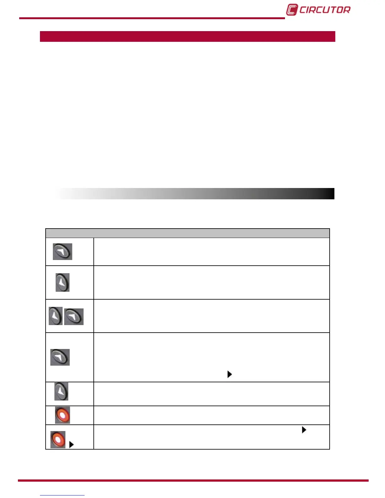
Table 14:Functions of the device in normal run mode�
Functions of the device in normal run mode
long
Manual connection of capacitor stages: Keep the key pushed during more than 1s
and the regulator will sequentially connect the different steps, following the normal pro-
gram and respecting the delay time t
on
long
Manual disconnection of capacitor stages: Keep the key pushed during more than
1s and the regulator will sequentially disconnect the different steps, following the normal
program and respecting the delay time t
off
set in the set-up procedure
Displaying the number of connected steps: If both keys are simultaneously pushed
the device displays the Nr of connected steps. Remember the difference between step
andstage(“2.3.3.- STAGES AND STEPS”)
short
Parameters measurement: Performing successive short pushing of this key (<1 s),
the user can travel along several display screens showing the values of the following
parameters:(cos),cosinusφoftheinstallation;(I),mainscurrent;(THD),THDofmains
current;(V) ,Mainsvoltage; (I,MAX),Maximum valueofmains currentsincethe last
clear;(VMAX),Maximumvalueofmainsvoltagesincethelastclear.
The displayed parameter is pointed by the cursor
short
Parameters measurement: Performing successive short pushing of this key (<1 s),
the user can travel through the readings of the same parameters described above but in
reverse order.
long
Start the SET-UP mode: Performingalongpushofthiskey(<1s),thedevicejumpsto
set-up mode.
MAX
Clear MAX values:Performingalongpushofthiskey(<1s)whilethecursor
is
pointing to MAX , the computer MAX clears the maximum values of voltage and current
recorded since the last clear.