6�- CONFIGURATION
6.1.- CONFIGURABLE PARAMETERS
In order to adapt the regulator to the loads, certain parameters of the Computer MAX must be
set-up. The programmable parameters, the required settings and the set-up procedure are ex-
plained here below. See also paragraph
“5.5.2.- KEY FUNCTIONS IN SET-UP STATUS” to see
how to select the different menu options.
Thecongurableparametersarelistedandshortlyexplainedbelow.
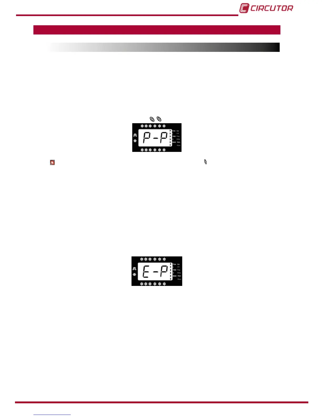
6�1�1�- PLUG&PLAY FUNCTION
To access the Plug&Play screen, press the
buttons to open the following screen:
Press to start the process; if you want to stop the process, long , and it will return to its initial
state.
Oncestarted,thedigitswillstartashingandthedevicewillstartacapacitormeasurement,
calculation and connection and disconnection process to gather the following capacitor bank
parameters: Phase (“6.1.8.- U, I PHASE ANGLE SETTING.”) y C/K Factor (“6.1.3.- SMALLER
AVAILABLE CAPACITOR STEP”
).
Oncethedevice’sPlug&Playprocesshasnishedandnoerrorhasoccurredduringthepro-
cess, the calculated C/K factor and the measured cosine phi will be displayed on the screen,
theresultofhavingcorrectlyconguredthephaserelationships(2timeseach).
If an error occurs during the process, the following screen will appear:
Conditions for the correct operation of the Plug&Play function:
The system should be maintained with an inductive cosine of 0.62 to 0.99 throughout the
process.
Thepowerinthesystemshouldbestable.Anymajorloadchanges(>10%inlessthan20
seconds) would result in an incorrect calculation of the capacitor power ratings.
There must be enough current in the system at the regulator’s input, i.e., >100 mA AC.
If the load is unbalanced, the correct operation of the Plug&Play function will depend on the
phase to which the current transformer is connected.
The correct values for Program (“6.1.5.- STAGE’S CONFIGURATION OF PF CORRECTION
EQUIPMENT (CONFIGURATION PROGRAM)”
) and Number of steps (“6.1.7.- SELECTION OF
THE NUMBER OF STAGES”
)mustbeconguredbeforehand.