ofstagescanbegivenintermsofmultiplesofthesmallerstep.Thenwecouldstatethecong-
uration(congurationprogram)ofPFequipmentas:
Program 1:1:1… All the stages have the same power in kvar.
Program 1:2:2… The second stage and successive have a power double than the 1st step.
Program 1:2:4… The 2nd step has double power and the successive quadruple that the 1st
step
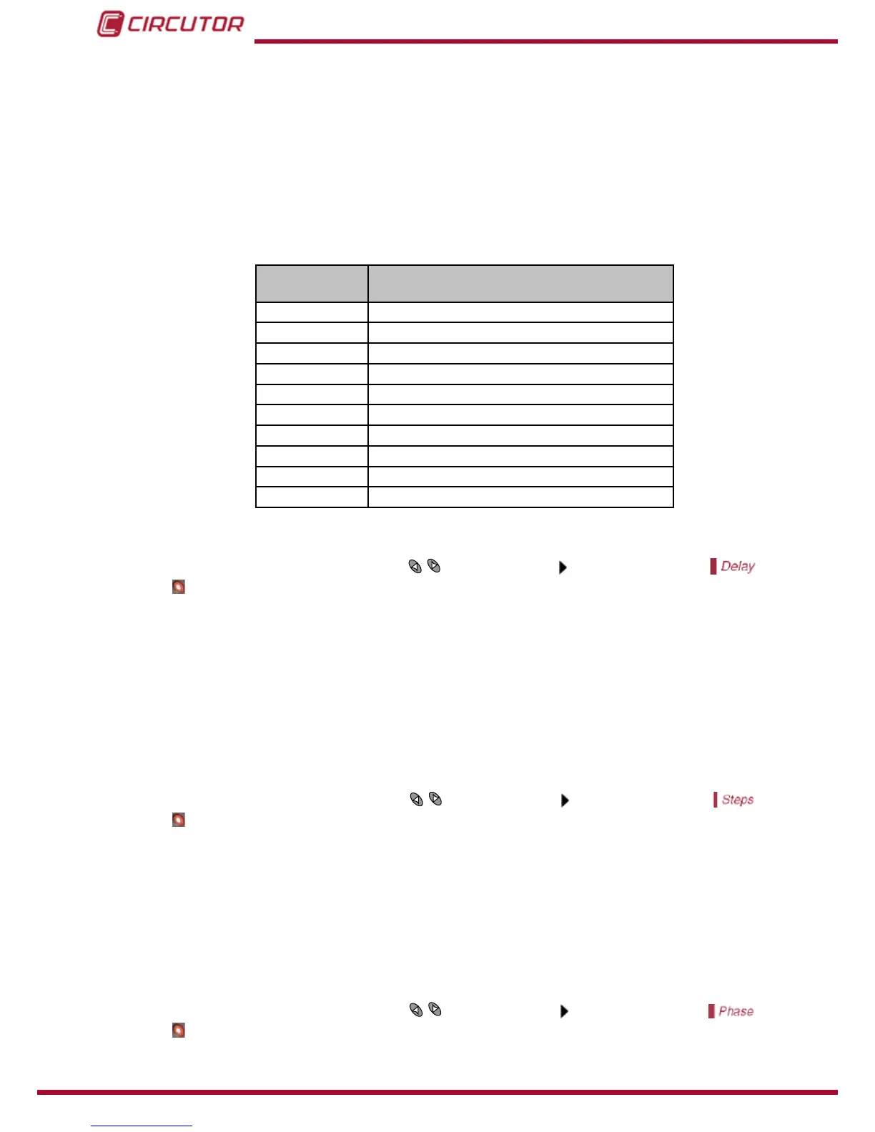
The default factory setting of computer MAX devices is 1:1:1:1. The available programs are:
Table 11:Available conguration programs for computer MAX
Screen
Indication
Stage’s conguration
111 1:1:1:1:1....
122 1:2:2:2:2....
124 1:2:4:4:4....
248 1:2:4:8:8....
112 1:1:2:2:2....
224 1:2:2:4:4....
123 1:2:3:3:3....
234 1:2:3:4:4....
236 1:2:3:6:6....
246 1:2:4:6:6....
6�1�6�- CONNECTION AND RE-CONNECTION TIME SETTINGS
To set-up this parameter, use the keys
until the cursor points to the option
, then
push .
This parameter sets up the delay times of the device. The setting value, Tc, is the delay time
between the connection or disconnection of successive capacitor stages. The parameter also
sets up the called reconnection delay, Tr, which is the minimum time that must elapse between
the disconnection of a C stage and its following connection. The range of Tc settings goes from
4sto999s.Tr is automatically set to 5 times Tc(NoticethatTr is needed to guarantee the
capacitors discharge). The default setting of Tc is 10 s�
6�1�7�- SELECTION OF THE NUMBER OF STAGES
To set-up this parameter, use the keys
until the cursor points to the option , then
push .
This setting allows the selection of the number of stages of the PF compensation equipment.
Depending on the device type, computer MAX 6 or MAX 12 we can select up to 6 or 12 stages.
If the number of stages is less than 6 or 12 respectively in computer MAX 6 or MAX 12 the
relay number 6 or 12 is automatically assigned as alarm relay. See “5.4.- ALARM RELAY”.
6�1�8�- U, I PHASE ANGLE SETTING�
To set-up this parameter, use the keys
until the cursor points to the option , then
push .