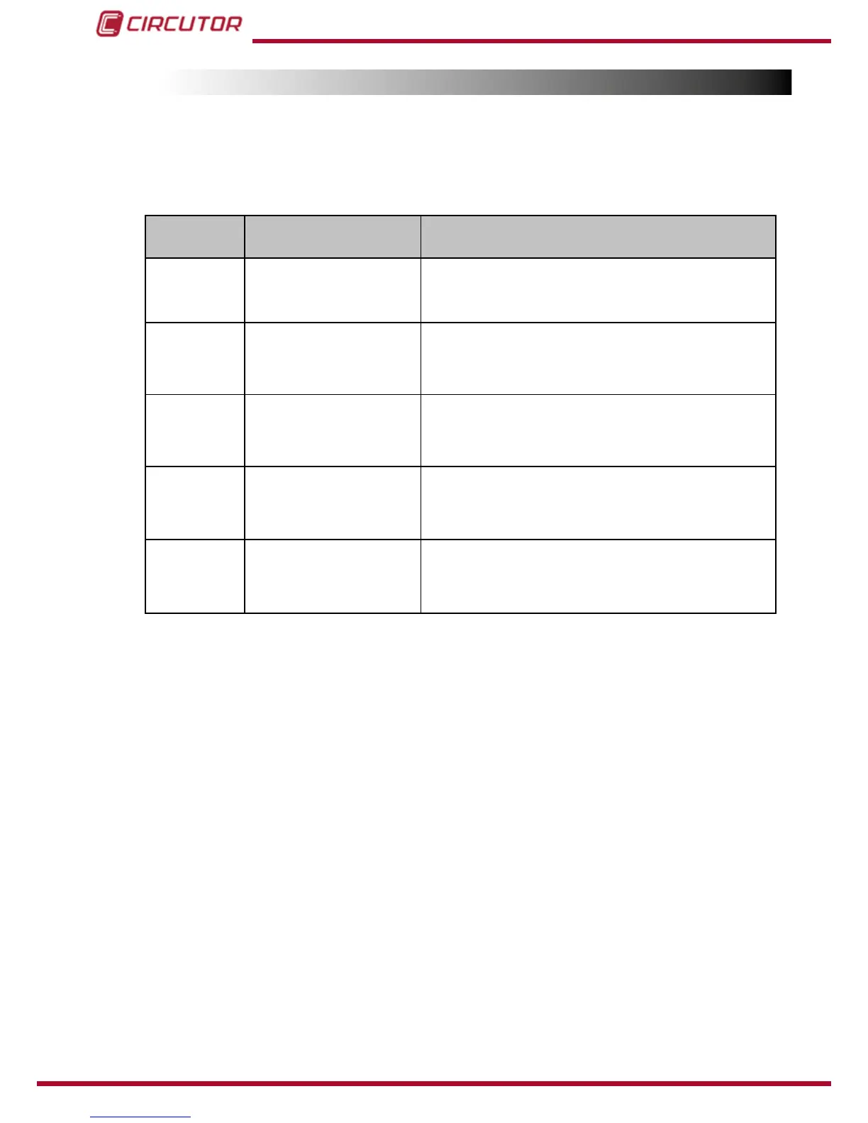
7.2.- computer MAX BEHAVIOUR IN ALARM MODE
In case that the computer MAXdetectsanerrorduringnormaloperation(see
“5.3.- ERRORS
AND ERROR MESSAGES”
), the screen displays an error code and the behaviour of the device
is as described in
Table 15
Table 15: Computer MAX behaviour under alarm conditions
ERROR
message
Description Possible cause and computer MAX behaviour
E01
Measured current below
threshold (0,05A measu-
red at the secondary side
of CT)
Possible causes: Low load or CT not connected.
The device shows the RUN LED and the screen with
everything blinking zeros and does not connect any relays
E02
Over-compensation� The
controller demands for
stages disconnection and
they are all disconnected
Possible causes: C/K not properly adjusted
None of the realys will connect.
E03
Sub-compensation� The
controller demands for
stages connection and they
are all connected.
Possible causes: C/K not properly adjusted
All the relays will remain connected, except the alarm relay
if exists (see
“5.4.- ALARM RELAY”)
E04
Overcurent� The measu-
red current is 20% above
the rated current (primary
of CT)
Possible causes: C/K not properly adjusted Alarm relay,
if exists, disconnects (see
“5.4.- ALARM RELAY”). Although
the regulation may be wrong, the device tries to
regulate the PF normally.
E05
Overvoltage� The measu-
red voltage is 15% above
rated voltage.
Possible causes: Connection to a wrong supply voltage.
Alarmrelay,ifexists, disconnects(see
“5.4.- ALARM RE-
LAY”
). Although the regulation may be wrong, the device
tries to regulate the PF normally.