2-2
Cisco TelePresence System 3000
OL-14521-01
Chapter 2 Building the Display Assembly
Parts List
Caution The display structures are unstable during assembly. Use caution, and support all structures as required.
Caution Some system components have metal and plastic edges with hard angles. These edges are exposed until
you complete system assembly. Use caution when you move around the system during assembly to avoid
contact with any exposed system edges.
Warning
Only trained and qualified personnel should be allowed to install, replace, or service this equipment.
Note The directions left and right refer to the assembly as you face the Plasma displays.
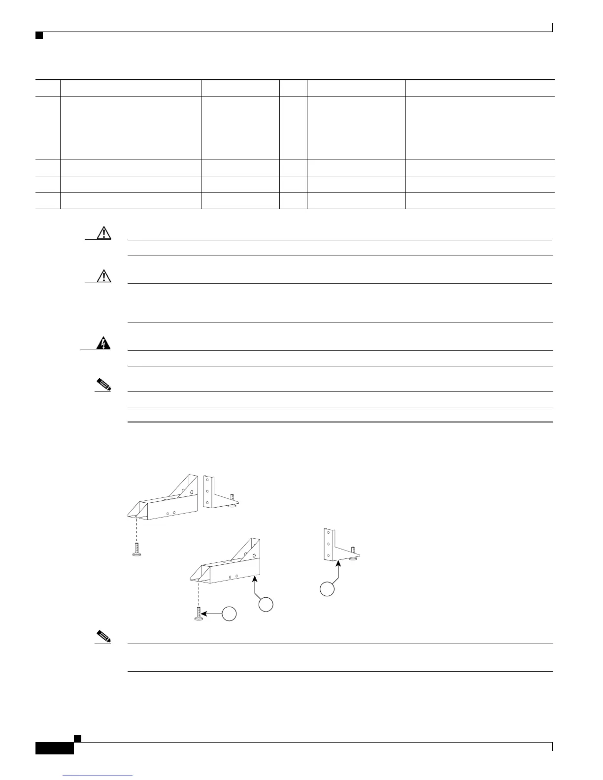
Step 1 Attach the Leveling feet to the Rear and Front Foot stabilizers.
Figure 2-1 Leveling feet
Note The structure becomes heavier and more difficult to move during the building process. Figure 2-9 shows
the correct positioning of the display structure; keep this in mind as you build the structure.
10
Support crossbars 700-23361-xx 4 33 (CTS3K-FUR-
MAPLE)
30
(CTS3K-M-TABLE-
G2)
11
M8 x 70 mm screws 48-2274-xx 1
12
M8 washers 49-1165-xx 1
13
M8 x 20 mm screws 48-2273-xx 1
Key Part Description Part Number Qty Ctn Notes