EasyManuals Logo

Cisco 4351 ISR User Manual

Cisco 4351 ISR
230 pages
To Next Page IconTo Next Page
To Previous Page IconTo Previous Page
Page #207 background imageLoading...
Page #207 background image
6-55
Hardware Installation Guide for Cisco 4000 Series Integrated Services Routers
OL-32185-02
Chapter 6 Install and Upgrade Internal Modules and FRUs
PoE Converter Power Supply Unit
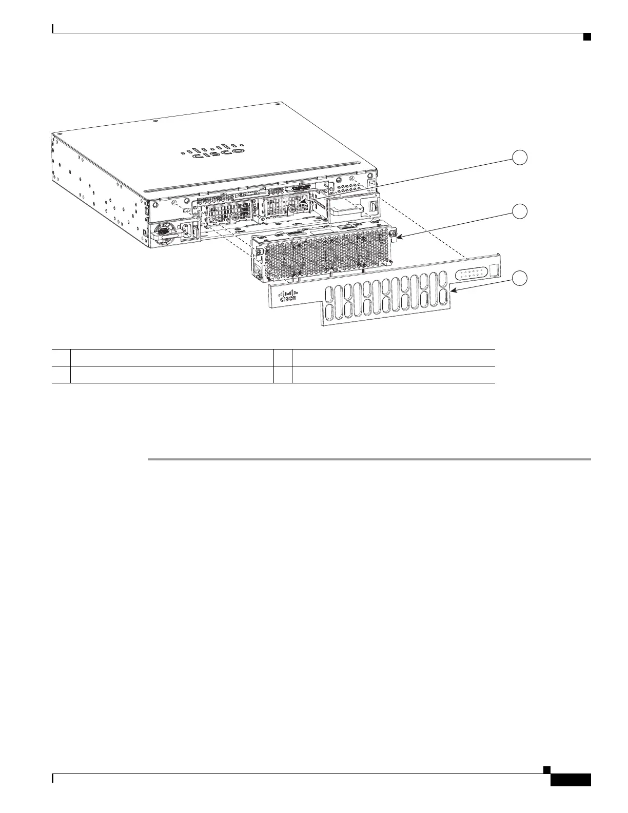
Figure 6-40 Remove Bezel and Fan Tray to Locate PoE Slots
Remove PoE Power Supply Slot Filler
To remove a PoE power supply filler:
Step 1 Remove the bezel and fan tray from the router.
Step 2 Loosen the screws from the securing nuts on the chassis. See Figure 6-41 for details.
Step 3 Gently pull out the filler from the filler tab on the chassis.
1 PoE converter power supply slot 2 Fan tray
3 Bezel
1
2
3
391817

Table of Contents

Questions and Answers:

Question and Answer IconNeed help?

Do you have a question about the Cisco 4351 ISR and is the answer not in the manual?

Cisco 4351 ISR Specifications

General IconGeneral
Form FactorRack-mountable
Integrated ServicesYes
LAN Ports4
Redundant power supplyOptional
Rack height1 RU
Product Series4000 Series
USB Ports2
Console Port1
Auxiliary Port1
Operating SystemCisco IOS XE
Maximum Throughput2 Gbps
Memory4 GB
Flash Memory4 GB (expandable to 16 GB)
Total concurrent sessions1, 000, 000
Model4351
ProcessorMulti-core
Network InterfacesGE, SFP

Related product manuals