2
Cisco 5520 and 8540 Wireless Controller Troubleshooting Guide
Overview of Cisco 5520 Wireless Controller
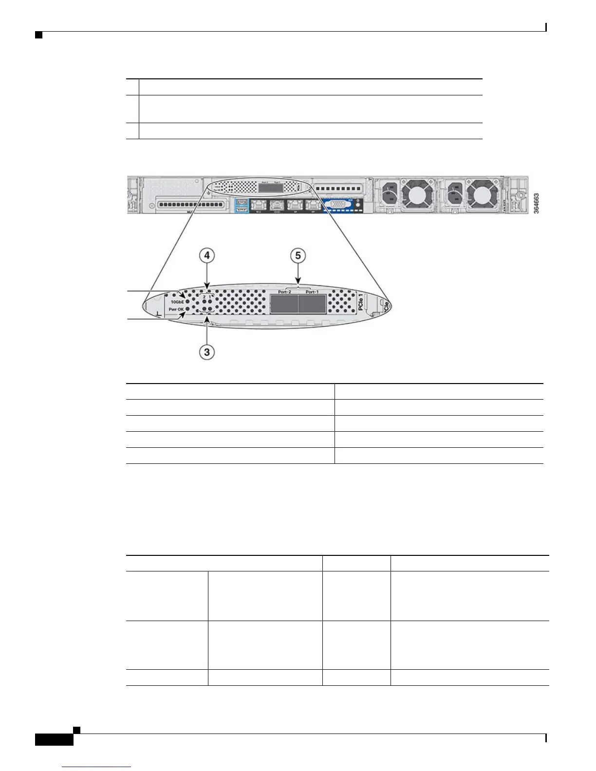
Rear Panel LEDs, Definitions of States
Table 1 lists the Cisco 5520 Wireless Controller Rear Panel LEDs, Definitions of States.
5 Redundancy Port (RP)
6 VGA Connector—Rear panel has a standard VGA port using a female D-Sub-15
Connector
7 ID Switch and LED
1 10 G
2Pwr OK
3 Port-n Link Status
4 Port-n Link Activity
5 Two 1/10 G SFP/SFP+ Ports
Table 1 Cisco 5520 Wireless Controller Rear Panel LEDs, Definitions of States
LED Name Function State
Pwr OK —
Amber On—Power is good
10 G — Amber On—10 G mode
Amber Off—1 G mode
Port-n Link Status — Green On—Link is up
 Loading...