CHAPTER
4-1
Cisco Wide Area Virtualization Engine 7541, 7571, and 8541 Hardware Installation Guide
4
Installing Hardware Options for the
WAVE-7541, WAVE-7571, and WAVE-8541
This chapter provides basic instructions for installing hardware options in your WAVE-7541,
WAVE-7571, and WAVE-8541. These instructions are intended for technicians who are experienced with
setting up Cisco WAVE-7541, WAVE-7571, and WAVE-8541 hardware.
This chapter contains the following sections:
• Installing a Cisco WAVE Interface Module
• Replacing a Hard Disk Drive/Solid State Drive
• Replacing a Fan
• Replacing a Power Supply
Installing a Cisco WAVE Interface Module
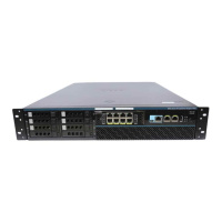
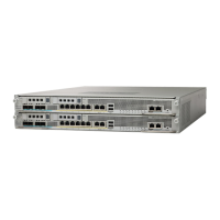
In addition to the two onboard Gigabit Ethernet ports, the WAVE-7541, WAVE-7571, and WAVE-8541
can accommodate one optional Interface Module:
• 4-port Gigabit Ethernet Copper Bypass Interface Module
• 8-port Gigabit Ethernet Copper Bypass Interface Module
• 4-port Gigabit Ethernet Fiber Optic Bypass Interface Module
• 2-port 10 Gigabit Ethernet Fiber Optic SPF+ Interface Module
For information on the features of the Cisco WAVE Interface Modules and cabling requirements, see
Chapter 5, “WAVE Interface Modules.”
Note Interface Modules are not hot-swappable therefore it is necessary to power the system down before
installing or replacing.
Caution To maintain proper system cooling, do not operate the appliance for more than 1 minute without either
a Cisco Interface Module or a filler panel installed in the bay.
To install a Cisco Interface Module in the Interface Module slot, follow these steps: