4-5
Cisco Wide Area Virtualization Engine 7541, 7571, and 8541 Hardware Installation Guide
Chapter 4 Installing Hardware Options for the WAVE-7541, WAVE-7571, and WAVE-8541
Replacing a Power Supply
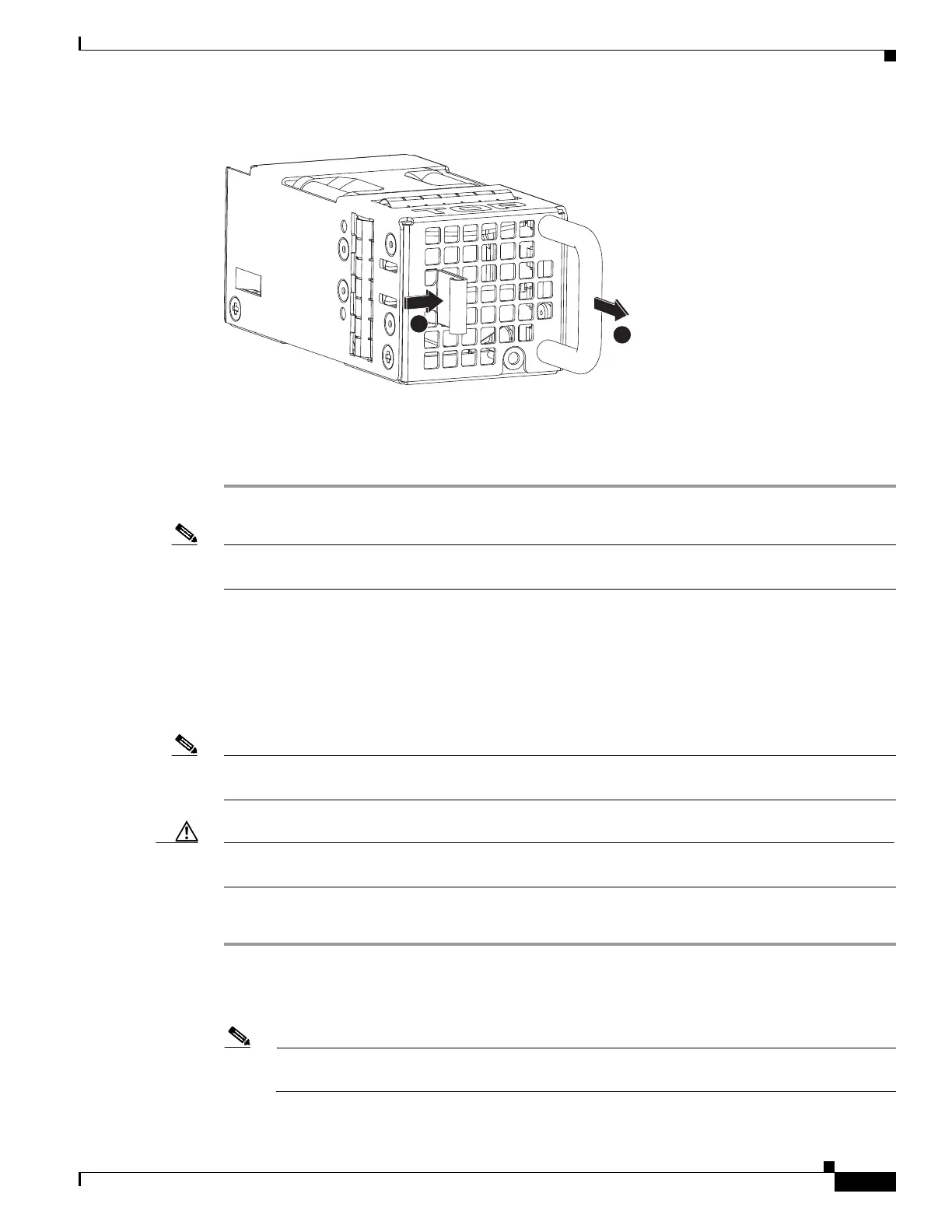
Figure 4-3 Fan Assembly
Step 3 Within one minute, insert the new fan with the surface marked “TOP” facing up and verify that the latch
is engaged.
Step 4 Check the power LED to verify that the new fan is receiving power.
Note If a fan alarm occurs and you power down the WAVE appliance to replace the fan, you must use the clear
bmc event-log global configuration command and then reboot to clear the alarm.
Replacing a Power Supply
The WAVE appliance supports two power supply assemblies that are hot-swap capable.
Power supply assemblies can only be inserted in one orientation.
Note Power supply assemblies must be inserted and can only function with the surface marked “TOP” facing
up.
Caution To maintain proper system cooling, do not operate the appliance for more than 1 minute without a power
supply installed in each bay.
To replace a power supply assembly, follow these steps:
Step 1 Review the information in the Safety Warnings and Cautions and Safety Guidelines sections in Chapter
2, “Preparing to Install the WAVE-7541, WAVE-7571, and WAVE-8541.”
Step 2 Remove the power cord from the power supply.
Note Power supply assemblies support load-sharing. If one loses power, the second power supply
takes over.