Step 2 Ensure that the DC circuit is powered down (either breaker turned off or fuse pulled) and proper lockout tag
out procedures are followed. Use the cable (PID: PWR-2KW-DC-CBL) supplied with the power supply. You
can purchase power supply cord separately from Cisco.
Step 3 Dress the power according to local practice.
Step 4 Connect the office battery and return cables according to the fuse panel engineering specifications.
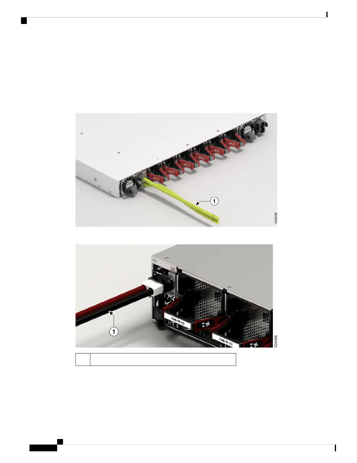
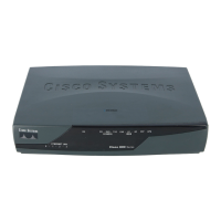
Step 5 Insert the DC connector into the DC receptacle on the power supply.
Figure 50: Connecting DC Power - Cisco 8711-32FH-M
Figure 51: Connecting DC Power - Cisco 8712-MOD-M
DC power cable1
Hardware Installation Guide for Cisco 8700 Series Routers
66
Powering on the Router
Connect DC Power to the Chassis



 To Next Page