EasyManuals Logo

Cisco 8851 Manual

Cisco 8851
48 pages
To Next Page IconTo Next Page
To Previous Page IconTo Previous Page
Page #17 background imageLoading...
Page #17 background image
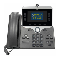
Step 4 Remove the two accessory connector covers, as shown in the diagram.
The slots are designed for the spine connector only. Insertion of other objects will cause permanent
damage to the phone.
Caution
Step 5 Position the phone so that the front of the phone faces up.
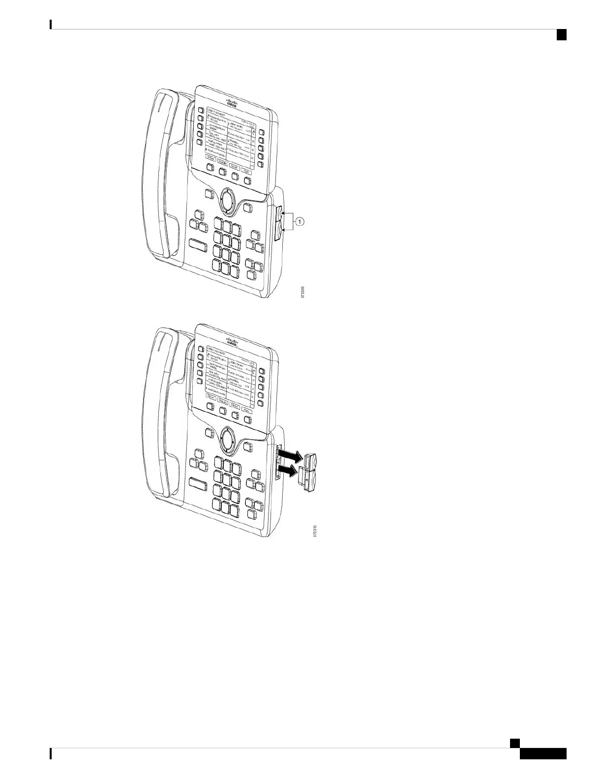
Step 6 Connect one end of the key expansion module spine connector to the accessory connector on the Cisco IP
Phone.
a) Align the spine connector with the accessory connector ports.
Install the connector in the orientation shown in the following diagrams.
Note
b) Firmly press the spine connector into the phone.
Cisco IP Phone Accessories
17
Cisco IP Phone Accessories

Table of Contents

Other manuals for Cisco 8851

Questions and Answers:

Question and Answer IconNeed help?

Do you have a question about the Cisco 8851 and is the answer not in the manual?

Cisco 8851 Specifications

General IconGeneral
Resolution800 x 480 pixels
Network InterfacesDual Gigabit Ethernet ports
Headset PortYes
AudioWideband audio
Ethernet10/100/1000 Mbps
USBYes, USB 2.0
PowerIEEE 802.3af/at Power over Ethernet (PoE)
ProtocolsSIP
PoEYes
Codec SupportG.711, G.722, G.729, iLBC
Headset ConnectorRJ9
LinesUp to 5 lines
Dimensions229 x 256 x 41 mm (excluding foot stand)
Weight1.2 kg

Related product manuals