EasyManuals Logo

Cisco 8851 Manual

Cisco 8851
48 pages
To Next Page IconTo Next Page
To Previous Page IconTo Previous Page
Page #20 background imageLoading...
Page #20 background image
Make sure that the screws are fully inserted into the phone and tightened.
If you lose any screws, the phone uses a standard M3 0.5x5.0mm screw.
Note
Step 11 (Optional) Install the footstands on the phone and on the key expansion module, and adjust both footstands
to rest evenly on the work surface.
Step 12 Plug the Ethernet cable into the phone.
Connect Two or Three Key Expansion Modules to a Cisco IP Phone
Procedure
Step 1 Unplug the Ethernet cable from the phone.
Step 2 If installed, remove the footstand from the phone.
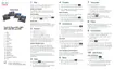
Step 3 Locate the accessory connector covers on the side of the phone.
This diagram shows the location.
Cisco IP Phone Accessories
20
Cisco IP Phone Accessories
Connect Two or Three Key Expansion Modules to a Cisco IP Phone

Table of Contents

Other manuals for Cisco 8851

Questions and Answers:

Question and Answer IconNeed help?

Do you have a question about the Cisco 8851 and is the answer not in the manual?

Cisco 8851 Specifications

General IconGeneral
Resolution800 x 480 pixels
Network InterfacesDual Gigabit Ethernet ports
Headset PortYes
AudioWideband audio
Ethernet10/100/1000 Mbps
USBYes, USB 2.0
PowerIEEE 802.3af/at Power over Ethernet (PoE)
ProtocolsSIP
PoEYes
Codec SupportG.711, G.722, G.729, iLBC
Headset ConnectorRJ9
LinesUp to 5 lines
Dimensions229 x 256 x 41 mm (excluding foot stand)
Weight1.2 kg

Related product manuals