EasyManuals Logo

Cisco 8851 Manual

Cisco 8851
48 pages
To Next Page IconTo Next Page
To Previous Page IconTo Previous Page
Page #19 background imageLoading...
Page #19 background image
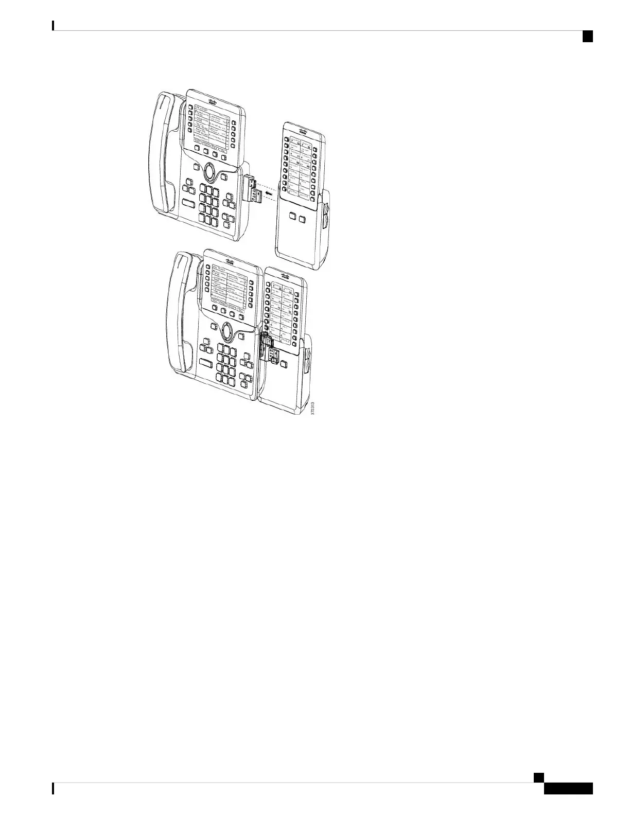
Step 8 (Optional) Use a second key expansion module spine connector to connect the second key expansion module
to the first key expansion module.
Step 9 (Optional) Use a third key expansion module spine connector to connect the third key expansion module to
the second key expansion module.
Step 10 Use a screwdriver to fasten the screws into the phone.
This step ensures that the phone and key expansion module remain connected at all times. This diagram shows
the location of the screw holes on the phone and one key expansion module.
Cisco IP Phone Accessories
19
Cisco IP Phone Accessories

Table of Contents

Other manuals for Cisco 8851

Questions and Answers:

Question and Answer IconNeed help?

Do you have a question about the Cisco 8851 and is the answer not in the manual?

Cisco 8851 Specifications

General IconGeneral
Resolution800 x 480 pixels
Network InterfacesDual Gigabit Ethernet ports
Headset PortYes
AudioWideband audio
Ethernet10/100/1000 Mbps
USBYes, USB 2.0
PowerIEEE 802.3af/at Power over Ethernet (PoE)
ProtocolsSIP
PoEYes
Codec SupportG.711, G.722, G.729, iLBC
Headset ConnectorRJ9
LinesUp to 5 lines
Dimensions229 x 256 x 41 mm (excluding foot stand)
Weight1.2 kg

Related product manuals