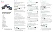
For cables that terminate outside of the bracket, use the cable-access openings in the bottom of the bracket to
position the power cord and any other cable that does not terminate in the wall behind the bracket. The phone
and wall bracket openings together form circular openings with room for one cable per opening.
Step 5 Proceed to Adjust the Handset Rest, on page 46.
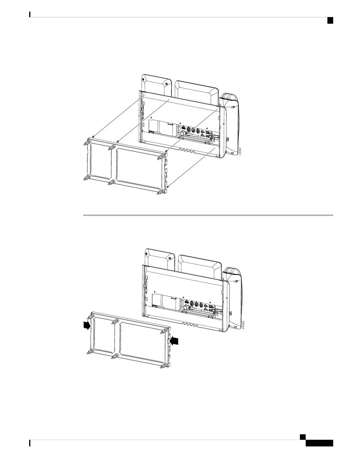
Remove the Phone and Key Expansion Module from the Non-Lockable Wall Mount
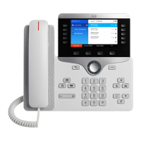
The wall bracket has two tabs that lock the kit together. Use the following illustration to locate the tabs.
Before you begin
Obtain two Phillips head screwdrivers or other similar devices that have a diameter of 5 millimeters or 3/16ths
of an inch.
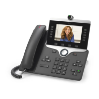
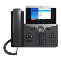
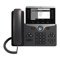
Cisco IP Phone Accessories
45
Cisco IP Phone Accessories
Remove the Phone and Key Expansion Module from the Non-Lockable Wall Mount
 Loading...